PLC Subroutines Manual
6FC5397-0FP40-0BA0, 08/2013
73
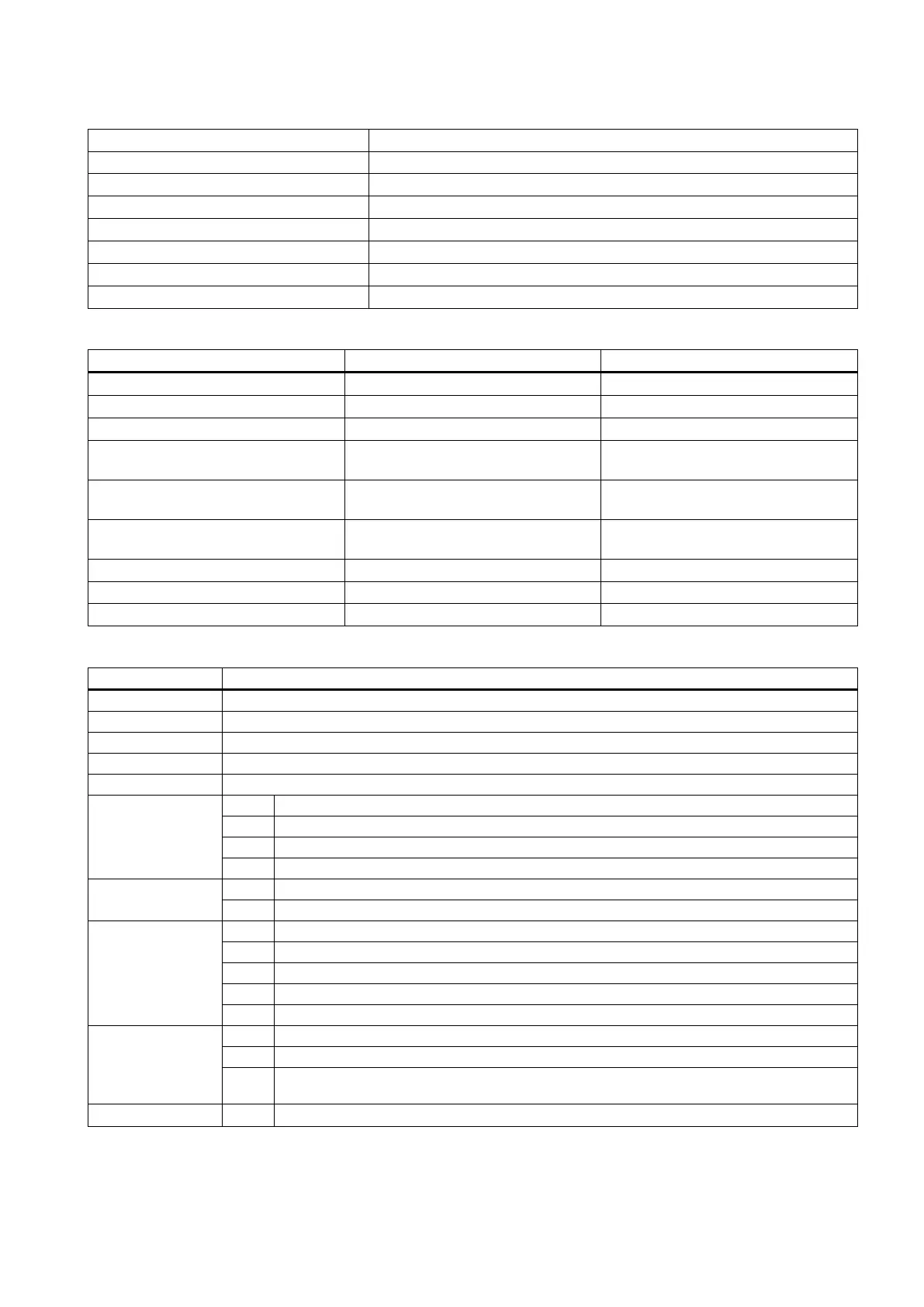
Table 5-4 Definition of user-defined keys on the MCP
User-defined key 1 Working lamp
User-defined key 2 Manual cooling
User-defined key 3 Safe door
User-defined key 4 Manual clockwise rotation of the tool magazine
User-defined key 5 Manual reset of the tool magazine
User-defined key 6 Manual counter-clockwise rotation of the tool magazine
User-defined key 7 Removing chip forward
User-defined key 8 Removing chip backward
Structure of the sample application (OB1)
Each scan (SM0.0) AUX_MCP (SBR20) Auxiliary function
First scan (SM0.1) PLC_INI (SBR32) PLC initialization
Each scan (SM0.0) EMG_STOP (SBR33) Emergency Stop control
Each scan (SM0.0) MCP_NCK (SBR37) Transferring MCP and HMI signals to
the NCK interface
Each scan (SM0.0) HANDWHL (SBR39) Selecting a hand wheel through the
interface signal DB1900.DBB1xxx
Each scan (SM0.0) AXIS_CTL (SBR40) Coordinate enabling control, hardware
limit, etc.
Each scan (SM0.0) SPINDLE (SBR42) Spindle control
Each scan (SM0.0) COOLING (SBR44) Cooling control
Each scan (SM0.0) LUBRICAT (SBR45) Lubrication control
Setting relevant PLC machine data
The maximum number of tool positions
Lubrication interval (in 1min)
Lubrication duration (in 0.01s)
14512[16]
When the function of safe door is active, it can be triggered by M01/M02
Handwheel assignment with the MCP / HMI
14512[17]
Selection between handwheel and hand-held unit (0: handwheel; 1: hand-held unit)
14512[18]
One time automatic lubrication after the power-on
Stop signal for an external spindle
Fixing the direction of a spindle
Hardware limit is independent of the PLC application
One hardware limit triggered per axis (enabled when bit 6=0)
14512[19]
Function of spindle braking
Password clearing by power-on (0: delete the password; 1: do not delete the password)
Bit 7 MM+ (Manual Machine Plus) function (enabled when the MM+ has been licensed and
corresponding PLC subroutine has been called)
14512[20] Bit 1 Spindle disable mode

 Loading...


