Design and Functional Principle
18
SIP ART PS2 Manual
A5E00074631-01
2.2.3 Pneumatic Connections
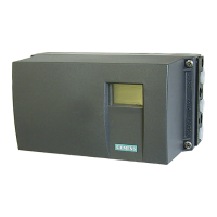
The pneumatic connections are on the right hand side of the positioner
(figure 2-3 and figure 2-4).
1
2
3
4
5
1 Actuating pressure Y1 in single-- and double--acting actuators
2 Feedback shaft
3 Supply air P
z
4 Actuating pressure Y2 in double--acting actuators
5 Exhaust air output E with silencer on the bottom of the instrument
Figure 2-3 Pneumatic connection in normal v ersion
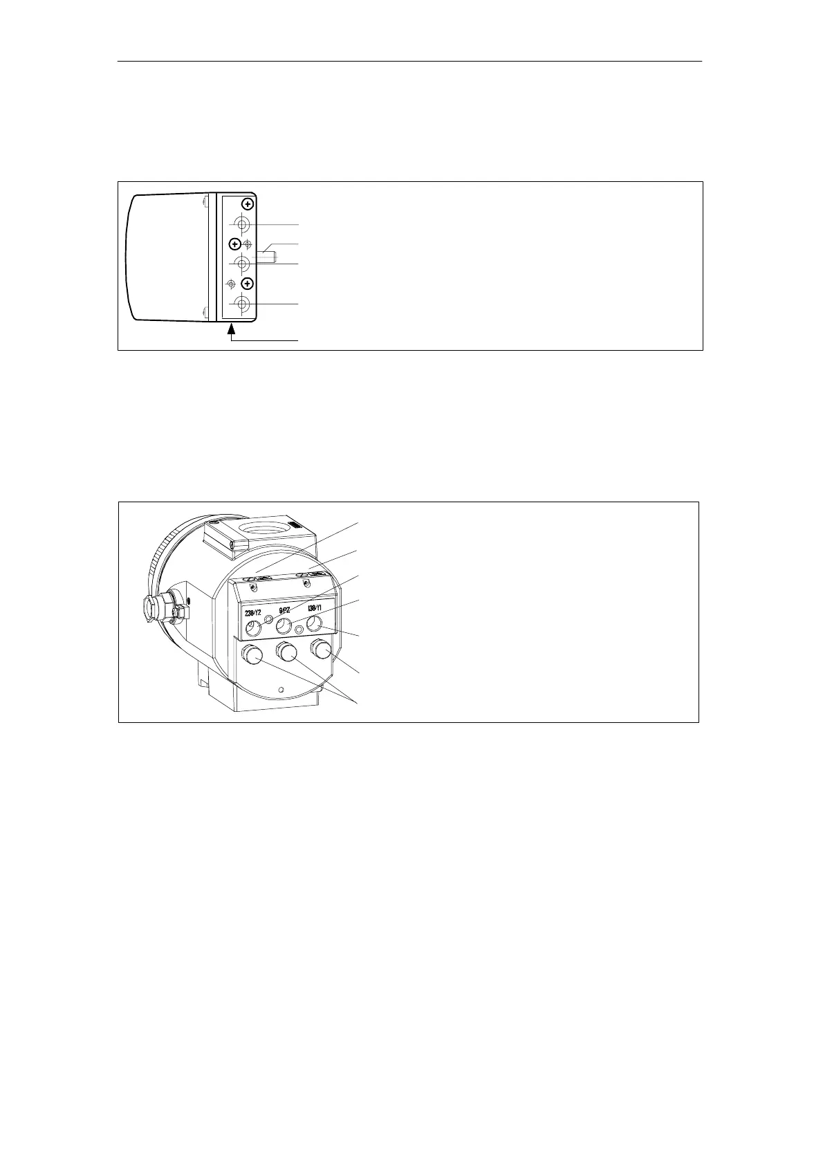
1
2
3
4
5
6
7
1 Restrictor Y2 *) 5 Actuating pressure Y1
2 Restrictor Y1 6 Exhaust air output E
3 Actuating pressure Y2 *) 7 Housing ventilation (2x)
4 Supply air PZ
*)
in double--acting actuators
Figure 2-4 Pneumatic connection in explosion proof version
In addition, there are pneumatic connections on the back of the positio-
ner for integrated installation in single--acting linear actuators.
- Actuating pressure Y1
- Exhaust air output E (not in explosion proof version)
In the ex--factory state, these connections are sealed by screws (see
figure 3-1, page 33, figure 3-3, page 34 and figure 3-4, page 35).
 Loading...