Preparing for Operation
58
SIP ART PS2 Manual
A5E00074631-01
3.6.1 Preparations for linear actuato rs
1. Assemble the positioner with the appropriate mounting kit (see
chapter 3.3.3, page 39).
.
NOTE
Particularly important is the position of the gear transmission switch (8,
figure 2-1, page 16) in the positioner:
Stroke Lever Position of the gear transmission
switch
5to20mm short 33° (i.e. down)
25 to 35 mm short 90° (i.e. up)
40 to 130 mm long 90° (i.e. up)
2. Push the carrier pin (4, figure 3-6 (page 41) 2) onto the lever (6,
figure 3-6, 2) to the scale position corresponding to the rated
stroke or next highest position and screw the carrier pin tight with
the nut (18, figure 3-6, 2).
3. Connect the actuator and the positioner with the pneumatic lines
and supply pneumatic power to the positioner (figure 2-3 and 2-4,
page 18 ).
4. Connect a suitable current or voltage source (see figure 3-12,
page 49 and figure 3-13, page 50).
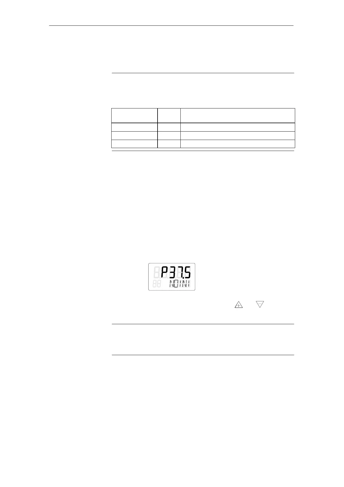
5. The positioner is now in the operating mode ”P-manual opera-
tion” The current potentiometer voltage (P) is displayed in percent
in the top line of the display, e.g.: ”P12.3”, and ”NOINI” flashes in
the bottom line:
6. Check the free running of the mechanics in the whole actuating
range by moving the actuator with the keys
and and driving
to the respective end position.
.
NOTE
You can move the actuator quickly by pressing the other direction key
additionally whilst keeping the direction key selected first pressed.
7. Now move the actuator to the horizontal position of the lever. A
value between P48.0 and P52.0 should be visible in the display. If
this is not the case, adjust the slip clutch (8, figure 2-10, page 27)
until ”P50.0” is displayed with a horizontal lever. The more
accurately you hit this value, the more exactly the positioner can
determine the path.
 Loading...