Preparing for Operation
39
SIP ART PS2 Manual
A5E00074631-01
3.3.3 Mounting kit ”linear actuator” 6DR4004-8V and 6DR4004-8L
The scope of delivery of the mounting kit” linear actuator IEC 534
(3 mm to 35 mm)” are contained (ser. no. see figure 3-6, page 41):
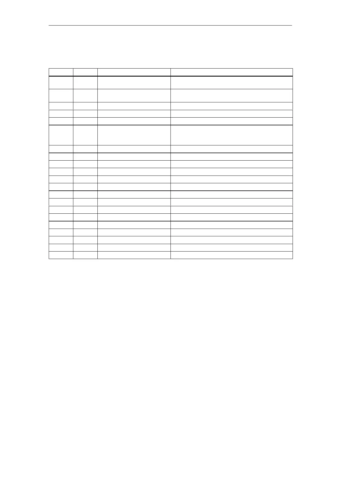
Ser. no. pieces Designation Note
1 1 NAMUR mounting kit bracket
IEC 534
Standardized connection for mounting console with
ledge, column or plane surface
2 1 Pick--up bracket Guides the roller with carrier pin and turns lever
arm
3 2 Clamping assembly Mounting of pick--up bracket on actuator spindle
4 1 Carrier pin Assembly with roll (5) on lever (6)
5 1 Roll Assembly with pin (4) on lever (6)
6 1 Lever NAMUR Forstrokerange3mmto35mm
For stroke ranges> 35 mm to 130 mm (special deli-
very), lever 6DR4004-8L is required additionally
7 2 U bolt Only for actuators with columns
8 4 Hexagon head screw M8 x 20 DIN 933-A2
9 2 Hexagon head screw M8 x 16 DIN 933-A2
10 6 Lock washer A8 -- DIN 127-A2
11 6 Flat washer B 8,4 -- DIN 125-A2
12 2 Flat washer B 6,4 -- DIN 125-A2
13 1 Spring VD-115E 0.70 x 11.3 x 32.7 x 3.5
14 1 Spring washer A6 -- DIN 137A-A2
15 1 Lock washer 3.2 -- DIN 6799-A2
16 3 Spring washer A6 -- DIN 127-A2
17 3 Socket cap screw M6 x 25 DIN 7984-A2
18 1 Hexagon nut M6 -- DIN 934-A4
19 1 Square nut M6 -- DIN 557-A4
21 4 Hexagon nut M8 -- DIN 934-A4
22 1 Guide washer 6.2 x 9.9 x 15 x 3.5
3.3.4 Assembly procedure (see figure 3-6, page 41)
1. Mount clamping assembly (3) with hexagon socket cap screws
(17) and lock washer (16) on the actuator spindle.
2. Insert the pick--up bracket (2) into the recesses of the clamping
assembly. Set the necessary length and tighten the screws so that
the pick--up bracket can still be shifted.
3. Push the roll (5), spring (13) and guide washer (22) onto the pin (4).
4. Insert the pin in the lever (6) and assemble with nut (18), spring
washer (14) and washer (12).
5. The value of the stroke range specified on the actuator or if this
does not exist as a scaling value, the next greatest scaling value is
set. The center of the pin must be in line with the scaling value.
The same value can be set later under parameter 3.YWAY in
commissioning to display the way in mm after initialization.
6. Assemble the hexagon socket cap screw (17), spring washer (16),
washer (12) and square nut (19) on the lever.
7. Push the premounted lever onto the positioner axis up to the stop
and fix with the hexagon socket cap screw (17).
 Loading...