SIPART PS2 (6DR5...)
A5E03436620-06, 04/2015
23
4.3 Pneumatic connection
Pneumatic auxiliary power
Owing to safety reasons, the pneumatic auxiliary power supply must be fed after installation only if the positioner is
switched to the "P-manual mode" when an electrical signal is available, refer to the as-delivered condition.
Note
Specifications regarding air quality
Observe the specifications regarding the air quality, see section "Technical specifications >
Pneumatic data (Page 39)".
● If required, connect the pressure gauge block for supply air and actuating pressure.
● Connection via female thread G¼ or ¼" NPT:
– Y1: actuating pressure 1 for single and double-acting actuators
– Y2: actuating pressure 2 for double-acting actuators
– Exhaust air outlet with a sound absorber. Remove the sound absorber if required.
● For double-acting actuators, connect actuating pressure Y1 or Y2 depending on the desired safety setting.
● Safety position in case of electrical auxiliary power supply failure:
– Positioner with single-acting pneumatic system: Y1 vented
– Positioner with double-acting pneumatic system: Y1 ventilated (maximum actuating pressure), Y2 vented
– Positioner with Fail in Place pneumatic system: Hold Y1 and Y2 (current actuating pressure)
Note
Leakage
Besides continuous air consumption, a leakage can cause the positioner to try to compensate the position deviation. This
will result in premature we
ar in the entire control device.
• After installing the pneumatic connections, check the tightness of the entire control valve.
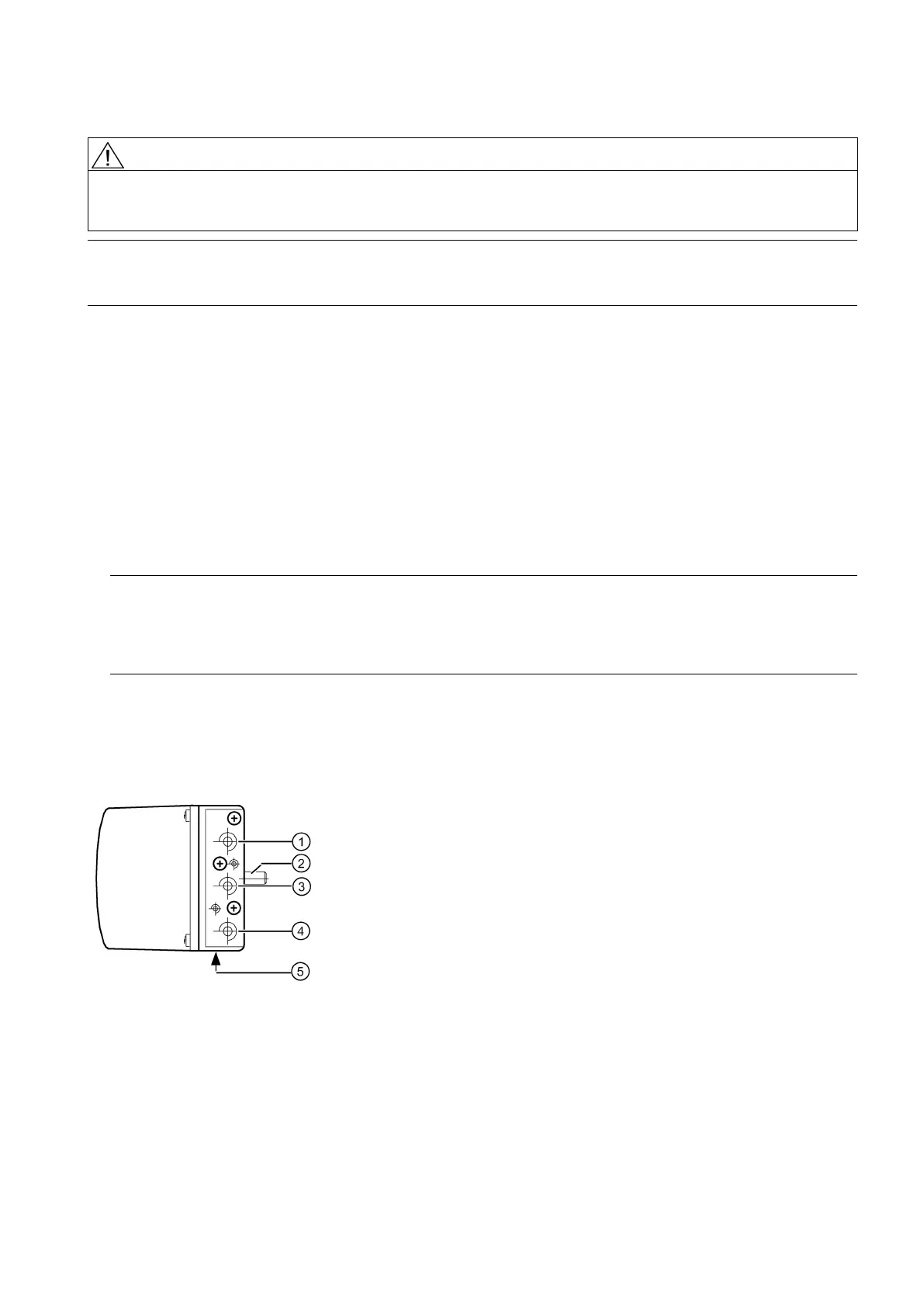
4.3.1 Pneumatic connection for 6DR5..0/1/2/3
Structure
The pneumatic connections are provided on the right side of the positioner.
Actuating pressure Y1 for single and double-acting actuators
Actuating pressure Y2 for double-acting actuators
Exhaust air outlet with a sound absorber
Figure 4-11 Pneumatic connection on the standard controller

 Loading...


