Configuring SIRIUS Innovations
Configuration Manual, 04/2010, A8E56203880102-02
91
Installation guidelines
6
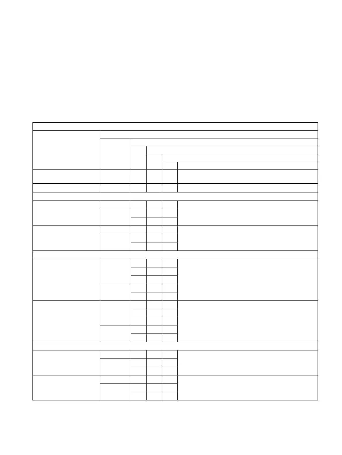
The table below provides an overview of the installation guidelines for fuseless load feeders
(sizes S00 and S0).
Table 6- 1 Installation guidelines – fuseless load feeders (sizes S00 and S0)
Combination
Output
Distance between feeders
Permissible installation: h = horizontal, v = vertical
Max. ambient temperature
Vibration and shock
1
Motor starter protector and
contactor
A mm h, v °C
3RA21 direct starter, screw terminal, DIN rail or wall
≤ 14 0 h, v 60
10 h 60
S00
14 … 16
0 h, v 40
Unlimited
≤ 29 0 h, v 60
10 h 60
S0
29 … 32
0 h, v 40
DIN rail adapter required
3RA21 direct starter, screw terminal, busbar
0 h 40
10 h 60
≤ 14
10 v 40
10 h 60
S00
14 … 16
10 v 40
Vibration and shock kit 8US1998-1CA10 required
0 h 40
10 h 60
≤ 29
10 v 40
10 h 60
S0
29 … 32
10 v 40
Vibration and shock kit 8US1998-1CA10 required
3RA22 reversing starter, screw terminal, DIN rail or wall
≤ 14 0 h, v 60
10 h 60
S00
14 … 16
0 h, v 40
DIN rail adapter required
≤ 29 0 h, v 60
10 h 60
S0
29 … 32
0 h, v 40
DIN rail adapter required
(already included with 3RA22)