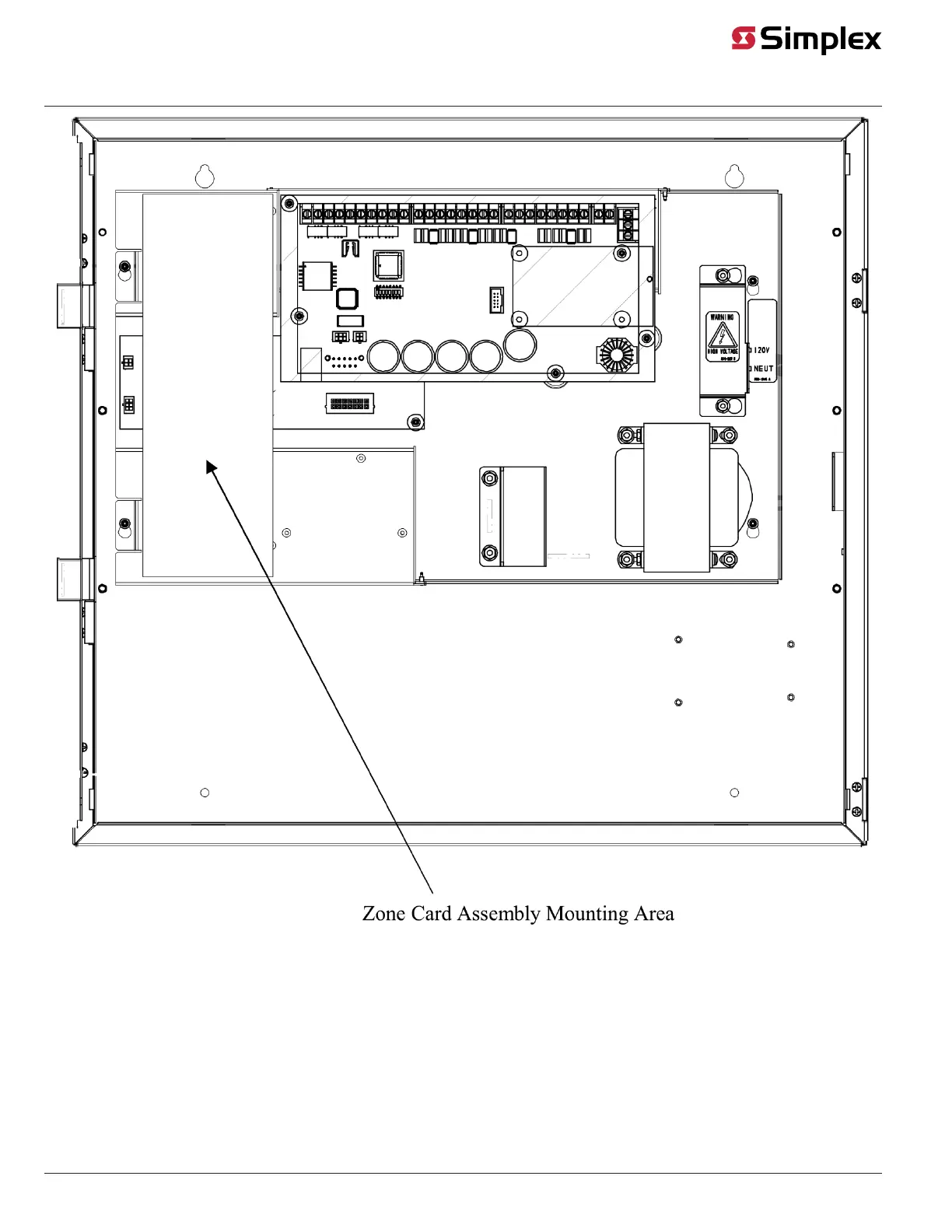
Figure 13: One-Bay Zone Card Mounting Area
Use the following directions to mount the Class A and B assemblies inside the 4010ES panel.
1. Attach the 8V DC Converter and the Zone Card Motherboard in the area indicated by Figure 13. Use the pre-drilled holes in the bay pan, as
well as stand-offs and metal screws as shown in Figure 10 and Figure 11.
2. Using harness 733-940, attach the 8V DC Converter to the Zone Card Motherboard. Connect the stripped end of the harness to connectors
"24C", "24+", "8C" and "8+" on the DC converter. Attach the other end of the harness to the top four pins on connector P3 of the Zone Card
Motherboard. The connectors are keyed to fit in only one direction. See Figure 14.
3. Attach the Core-4 connector on harness 734-244 to the Non-PDI Card Connection (P2) on the top-bay PDI.
4. Attach the flat 4-pin connector on harness 734-244 to the top four pins on connector P2 of the Zone Card Motherboard.
page 13 579-205 Rev. H
4010ES and 4100 4120-Series Class A/Class B Zone Modules Installation Instructions
 Loading...