Coronet / 2400 / RE 200 Series
14
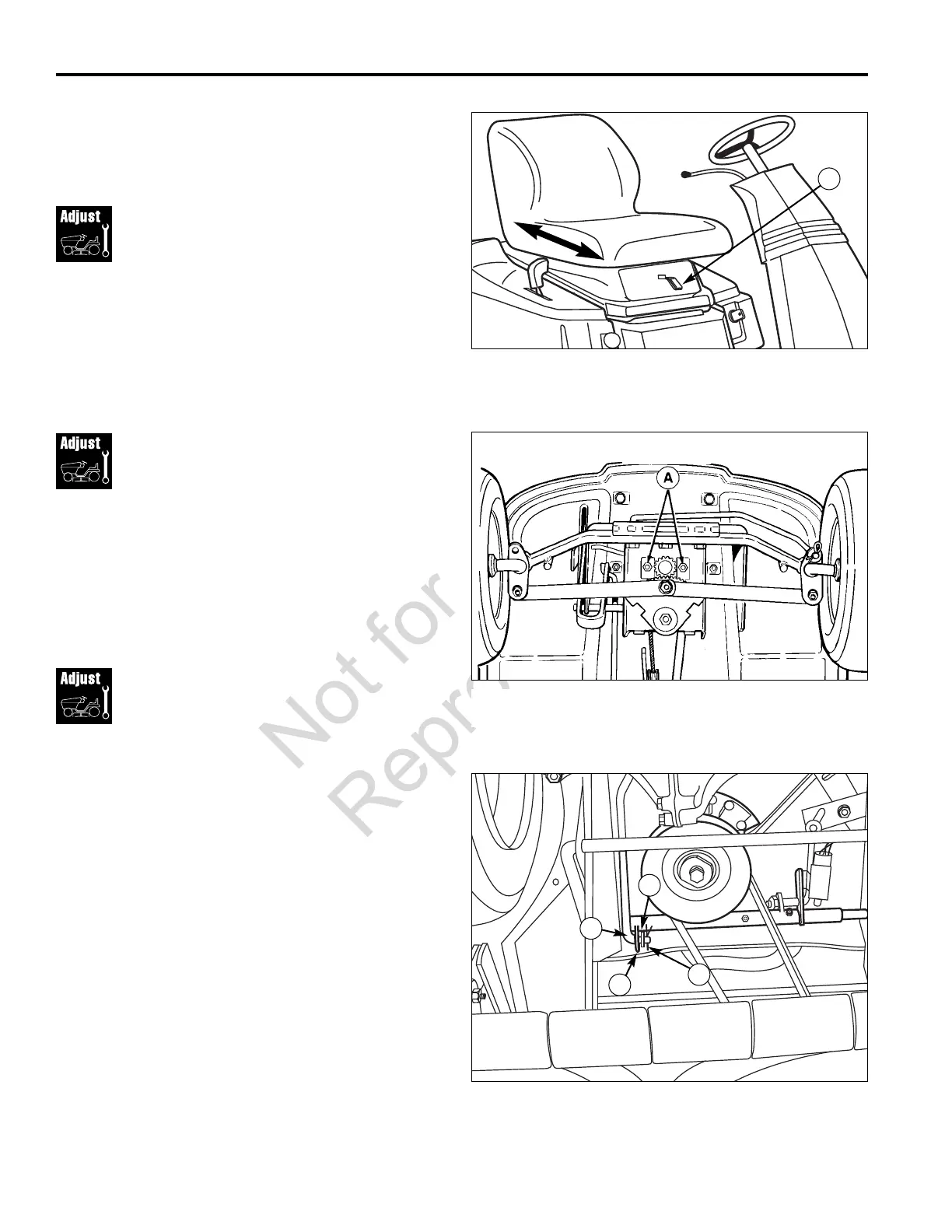
Steering Gear
Adjustment
If there is excessive slack in the steering system, the
steering gear can be re-indexed to the steering shaft.
1. See Figure 23. Loosen the two capscrews (A) and
push bracket so that gear teeth are closely meshed.
2. Tighten nuts after adjustment to 35 - 40 ft-lbs.
Seat Adjustment
Use the lever on the front of the seat (A, Figure 21) to
adjust the seat forward or rearward for best rider comfort.
Adjustment
Procedures
Figure 22. Seat Adjustment
A. Seat Adjustment Lever
A
Figure 23. Steering Gear Adjustment
A. Capscrews
*2401
Capscrews
Neutral Adjustment
Perform the following if the rider travels forward or back-
ward with the ground speed control lever in the neutral
gate.
1. Position the rider on flat, level ground and start the
engine.
2. Position the ground speed control lever so that the
rider has no forward or reverse movement. The
ground speed control lever may not necessarily be in
the neutral gate. Shut off the engine. Do not depress
the clutch/brake pedal or move the ground speed
control lever.
3. Remove hair pin (A, Figure 24) and washer (D) from
shift rod (B). Remove shift rod (B) from pivot shaft
assembly (C). Place shift lever into the neutral gate.
Turn shift rod (B) clockwise or counter clockwise
depending upon the direction the rider creeps.
4. Place shift rod (B) into pivot shaft assembly (C) and
secure with hair pin (A) and washer (D).
5. Repeat Steps 1 through 4 until the rider has no for-
ward or reverse movement when the ground speed
control lever is in the neutral gate.
Figure 24. Neutral Adjustment
A. Hair Pin C. Pivot Shaft Assembly
B. Shift Rod D. Washer
A
D
B
C
 Loading...