Coronet / 2400 / RE 200 Series
5
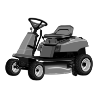
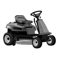
Tractor
Assembly (CE Only)
NOTE: The following assembly procedure is for Export
models only.
Seat Installation
1. The mounting hardware for the seat is retained in the
seat deck by push nuts. Position seat over four cap-
screws extending from bottom of seat deck, raise seat
deck, and tighten the four capscrews. Push nuts can
be left in position.
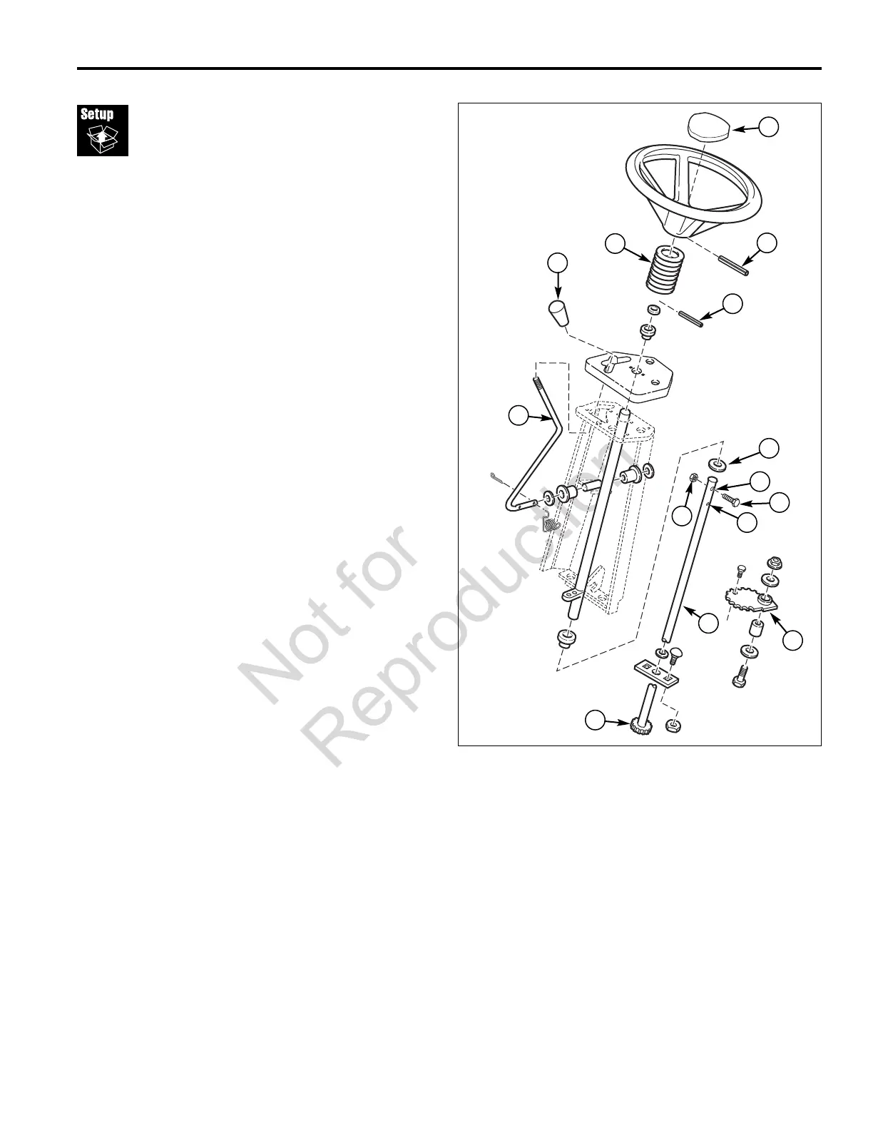
Steering Wheel Assembly
1. To install steering wheel, see Figure 3:
a. Hold steering shaft (H) and remove shipping hard-
ware (L).
b. Remove two plastic spacers shipped on top of
dashboard. Discard spacers. Retain flat washers.
c. Remove the steering shaft roll pin (D) from steering
cap (A, found in Literature Packet).
d. Raise the steering shaft (H) thru dashboard and
check the orientation of steering shaft hole before
engaging steering shaft gear (I) with sector gear
(G). Holes must be oriented at the 10:00 and 4:00
position for steering wheel orientation to be correct.
Make sure flat washers (K, 1-1/16" O.D.) are
installed and install roll pin (D) thru steering shaft
(H) into lower hole (F).
e. Install the rubber boot (M, found on mower lift han-
dle) over the steering shaft.
f. Install steering wheel using roll pin (B) into upper
hole (E). Install the steering wheel cap (A).
2. Install the knob (C) on the shift lever (J, knob found in
Literature Packet).
H
B
K
A
Figure 3.
A. Steering Wheel Cap H. Steering Shaft
B. Roll Pin 3/16 x 2-1/2 I. Steering Gear
C. Shift Knob J. Shift Lever
D. Roll Pin 3/16 x 1 K. Flat Washer
E. Upper Hole L. Shipping Hardware
F. Lower Hole M. Rubber Boot
G. Sector Gear
C
I
F
G
D
J
E
L
L
M
 Loading...