Coronet / 2400 / RE 200 Series
15
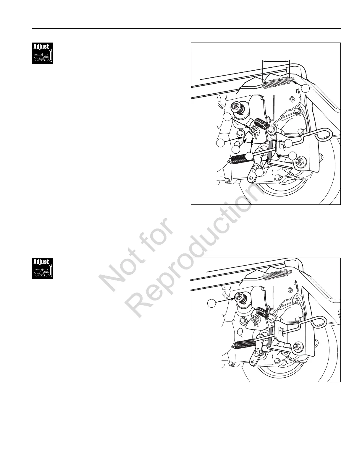
Brake & Brake Spring
Adjustment
1. Release the parking brake.
2. Brake arm (C, Figure 25) should be touching stop (B).
3. Remove cotter pin (D) and loosen the castle nut (A).
Place a 0.015” feeler gauge (E) gap between the
brake disc (F) and the brake puck (G).
a. To decrease gap, insert feeler gauge in gap and
turn nut (A) clockwise until resistance is felt on the
feeler gauge. To increase gap, turn nut (A)
counter-clockwise and recheck gap.
b. Back off nut (counter-clockwise) until the nearest
slot is aligned with hole in threads. Replace cotter
pin.
4. Set the parking brake. Loosen or tighten adjustment
nut (H) to achieve a 1-5/8” - 1-3/4” compressed spring
length as shown in Figure 24.
Figure 25. Brake Adjustment
A. Castle Nut E. Feeler Gauge
B. Stop F. Brake Disc
C. Brake Arm G. Brake Puck
D. Cotter Pin H. Adjustment Nut
E
B
F
A
C
D
H
1-5/8” - 1-3/4”
G
Ground Speed Lever
Resistance Adjustment
Adjusting the nut (A, Figure 26) in or out will change the
resistance to the ground speed lever.
1. Turn the nut in or out 1 to 2 turns at a time counting
and noting the number of turns.
2. Try the unit to see if the desired effect is achieved. If
not repeat Steps 1 and 2 again.
NOTE : The furthurest the nut can be loosened is until no
threads are showing.
Figure 26. Ground Speed Lever Resistance
Adjustment
A. Nut
A
 Loading...