6 S0100 / S0105 104 73 97-26
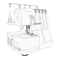
Setting of cams
This is checked to make sure so the cams are in its basic position.
Final setting of the each cam position is done when each individual setting has been perfor-
med.
1. To check the setting of the cams, remove the base plate fi rst.
2. For easier check also remove the hand wheel.
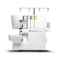
3. Set #1 point - the counter weight mark and fastening pin, so there are lined up against
the (B) screw on the casting. See illustration above.
4. The # 2 Cam - The Feed cam.
It should now be position so its fi rst set screw (a) is lining up
against the (B) screw on the casting.
NOTE! The lower shaft has a fl at spot where the Cam # 2's fi rst
screw (a) always must be positioned on.
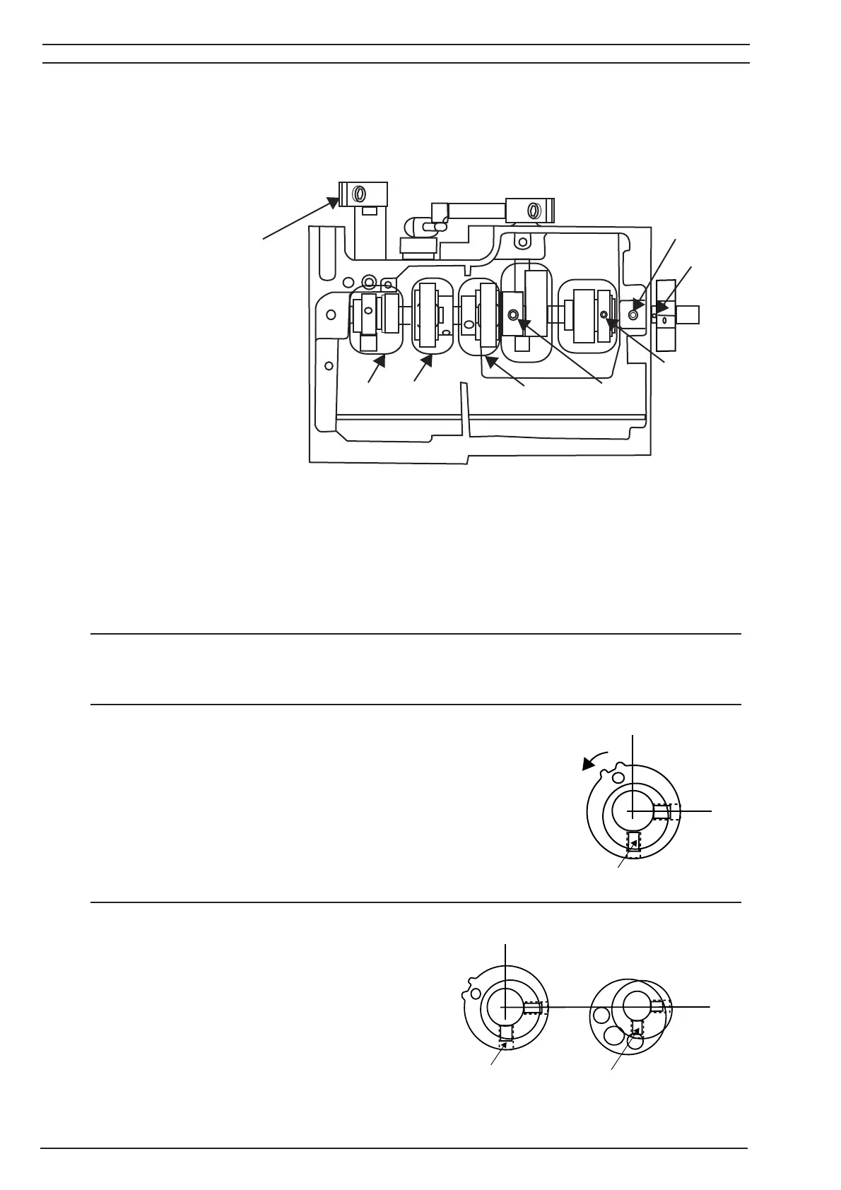
5. The # 3 Cam - The Needle bar eccentric cam.
It should now be position so its fi rst set screw (a)
is lining up against the (B) screw on the casting.
NOTE! The lower shaft has a fl at spot where the
Cam # 3's fi rst screw (a) always must be positio-
ned on.
#1 point - Pin In arm shaft and mark in counter weight
# 2 Cam - The Feed cam.
# 3 Cam - The Needle bar eccentric cam.
#4 Cam - Upper looper cam.
# 5 Cam - Lower looper cam.
# 6 Cam - Feed lifting cam.
B
1
2
3
4
5
6
a
X
a
X
 Loading...