Do you have a question about the SMC Networks EZ1026DT and is the answer not in the manual?
| Data Transfer Rate | 10/100 Mbps |
|---|---|
| Jumbo Frame Support | No |
| WAN Port Type | 1 x 10/100Base-TX |
| Power Supply | External |
| Firewall | Yes |
Details on IEEE standards compliance, port count, expansion slots, auto-negotiation, and management features.
Lists the items included in the SMC-EZ1026DT V.2 Switch package, such as the switch, rubber feet, rack-mount kit, and cables.
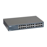
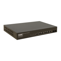
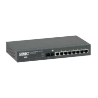
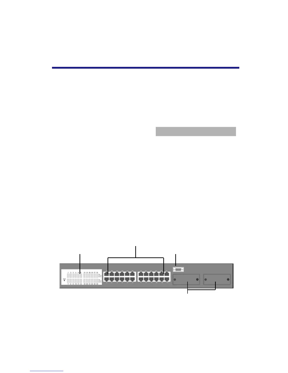
Describes the physical components including the front panel with RJ-45 ports, expansion slots, and console port.
Details the LED indicators for system status and the components located on the rear panel, including power connections.
Ensures necessary prerequisites like PCs with NICs, UTP/Fiber cables, and a suitable power outlet are met before installation.
Instructions for placing the switch on a flat surface, ensuring it's dust-free, and attaching rubber feet for stability.
Steps for mounting the switch in a standard EIA 19-inch rack using provided brackets and screws.
Details on using the console port and RS-232 cable to connect to a PC or terminal for monitoring and configuration.
Guides on establishing a console connection, setting communication parameters like baud rate, and logging into the interface.
Illustrates a small network topology for backbone connectivity, supporting heavy traffic users and server accessibility.
Details how the switch acts as a segment switch for enterprise departments, alleviating contention and improving throughput.
Explains using the switch for connecting workgroups, supporting high bandwidth and providing cost-effective alternatives to FDDI/ATM.
Describes grouping switch ports into broadcast domains for increased capacity, logically segmenting users by business policies.
Demonstrates how multiple VLANs can share resources like servers and printers, allowing access across different logical network segments.