HRX-OM-W004
Chapter 3 Serial communication
3.8
Message configuration HRR Series
3-8
3.8 Message configuration
3.8.1 Message frame
The message configuration is shown below. The communication of this
product uses 2 transmission modes, ASCII or RTU.
1) ASCII mode frame
For ASCII mode, the message starts with ASCII characters “:”(0X3A) and
ends with “CR/LF”(0X0D,0X0A). A response message will not be returned
unless the request includes [:] and [CR][LF]. This product clears all previously
received code when [:] is received.
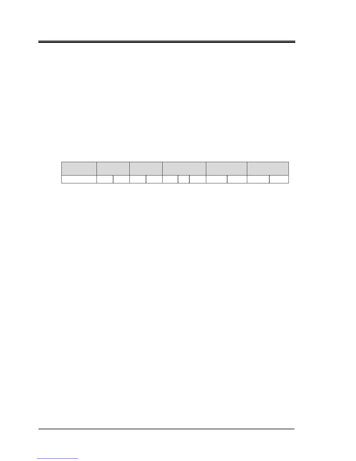
Table 3.8-1 ASCII mode message frame
a)Start
b)Slave
Address
c)Function d)Data
e) Checksum
(LRC)
f)End
[:] XX XX XX XX XX
~
XX XX XX [CR] [LF]
a) Start
The start of the message. [:](3Ah) (ASCII)
b) Slave Address
This is a number to identify this product. “1" is the default setting. This can
be changed by the operation display panel.
c) Function(
Refer to “3.9 Function codes”)
Command is assigned.
d) Data
Depending on the function, the address and the number of the register, the
value of reading/writing are assigned.
e) LRC
LRC method
Refer to ‘’3.10.1 LRC(ASCII)’’.
f) END
The end of the message. [CR](0Dh)+[LF](0Ah)

 Loading...