HRX-OM-W004
Chapter 1 Read before using
1.3
Key operations
HRR Series
1-4
1.3 Key operations
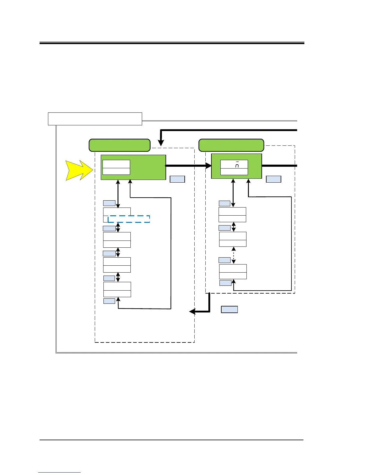
Fig 1.3-1‘’Key operation(1/4)’’ and
Fig1.3-4 ‘’Key operation(4/4)’’ show the operation of keys of the
thermo-chiller. This manual explains the “Communication setting menu”.
Fig 1.3-1 Key operation (1/4)
MENU
Main menu
Power supply ON
Allarm number
(Allarm number
maximum)
Alarm display menu
Allarm number
AL01
Allarm number
(Alarm number minimum)
AL02
ALXX
MENU
AL
XXALM
Basic setting mode
00
circulating fluid return
temp
014
Circulating fluid
outlet pressure
123
DIPV
Electric
conductivity∗
(μS/cm)
PRESS
79
Circulating fluid
flow rate
FLOW
RET ⇔ TEMP
▲/▼
▲/▼
▲/▼
▲/▼
▲/▼
▲/▼
▲/▼
▲/▼
▲/▼
200
200
Circulating fluid
outlet temperature
Circulating fluid set
temperature
∗ Option D【Electric conductivity control function】 only
RESET
Displays only when the alam is generated.

 Loading...