PTE-100-C
21
COMMUNICATIONS
The PTE-100-C features two different means of communicating with other
equipment: standard RS-232 and EuroSMC’s proprietary PTE-BUS commu-
nications. Both connectors are located on the center of the front panel
above the EuroSMC logo.
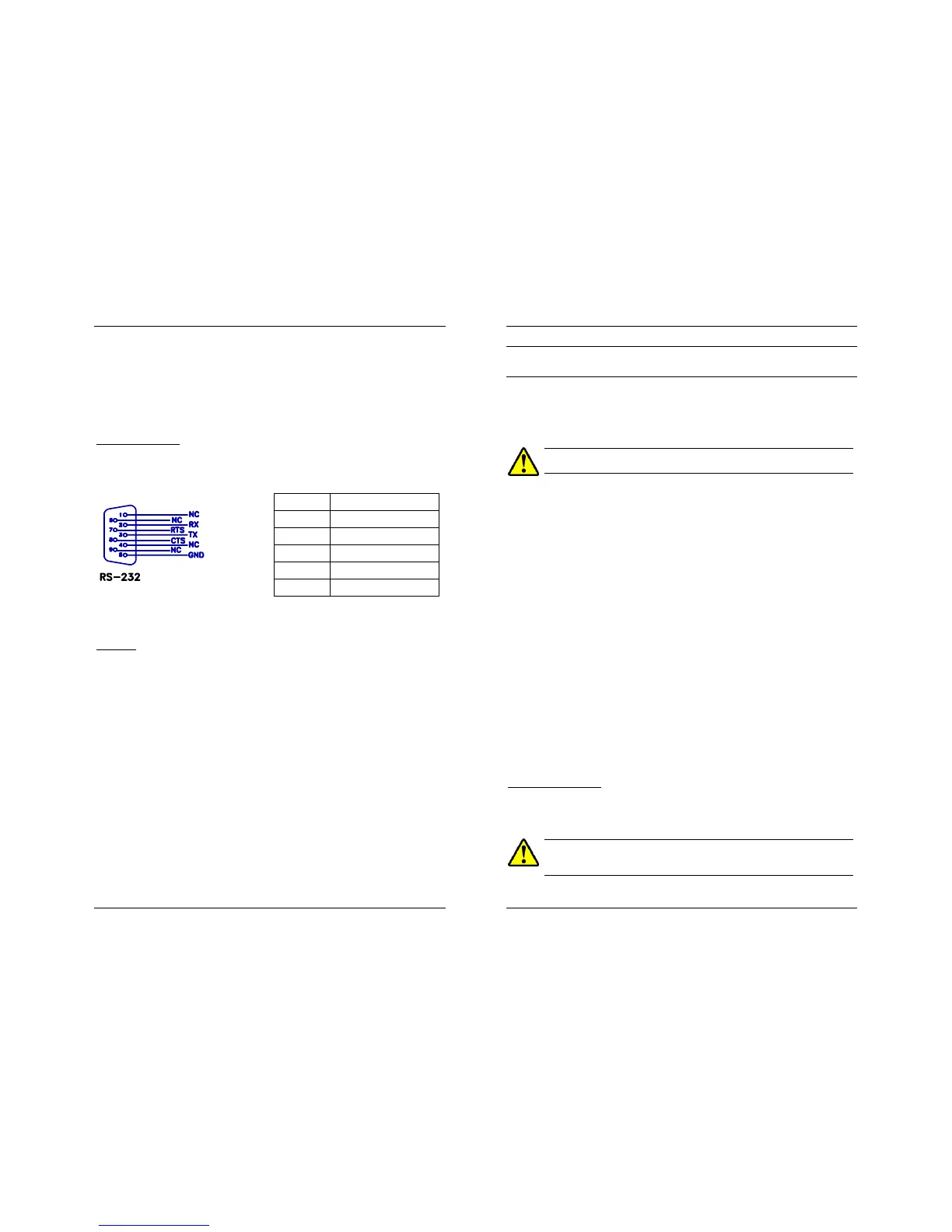
Serial RS-232 port
This standard DB-9 male connector is compatible with common serial de-
vices such as printers, data terminals and computers. Following is the RS-
232 pinout:
1,4,6,9: NC Not connected
5: GND Earth ground
2: RX Input DATA
3: TX Transmitted DATA
7: RTS Output - Ready to Send
8: CTS Input – Clear to Send
The unit is supplied with the appropriate cable for connection to a serial
printer or to a computer.
PTE-BUS
The PTE-100-C can be linked to other EuroSMC’s products over this special,
high-speed applications bus, in order to extend their capabilities. Thanks to
this advanced concept of modularity, the user can interconnect two or more
PTE units to build a sophisticated test platform that is more powerful and
capable than the individual sets used, whenever complex relay testing or
assistance from a computer is required.
USER’S MANUAL
22
OPERATION
As a test instrument, you basically use the PTE-100-C to adjust and apply
some electrical magnitudes to the tested device and to measure its response
time or other test results. Directions to use the features described in the pre-
vious section are given here.
DO NOT USE THE PTE-100-C FOR REAL TESTING BEFORE READING
AND FULLY UNDERSTANDING THIS SECTION.
CURRENT AND VOLTAGE INJECTION
You inject AC current into a load by applying AC voltage to it. Some tests
require current (Amperes) regulation and other require voltage (Volts) regu-
lation.
The various power outputs have been designed and built into the PTE-100-
C with these test requirements in mind. Therefore, to perform a current test,
the receiver must be connected to the appropriate current tap and regula-
tion must be done in Amperes. This is the default operation mode of the
PTE-100-C. Conversely, for voltage tests, we will connect the test object to
Out 1 or Out 2 and will set the Display #2 to voltage reading by means of
the corresponding display assignment button.
In any case, the electrical magnitudes to which the tested device is exposed
depend on the following factors:
1) the used output
2) the variac’s position
3) the connected impedance
AC Current Injection
To inject AC current, follow these steps:
1. Turn the variac knob to its leftmost position dialed “0”.
A harmful amount of current could be injected into the connected load
if you accidentally switch the output ON with the variac in a position
other than zero.

 Loading...
