PTE-100-C
27
So these are the basic steps for a time test:
1. Switch the PTE-100-C’s power output and turn the variac all
the way to the left to reach the “0” position.
2. Connect the relay’s measurement input (to where the CT or VT out-
put is normally connected) to the appropriate current or voltage
output tap.
3. If you are doing a current based test, choose the current tap that
better accommodates the regulation range, turn its ‘flag’ LED on
using the key and give a short press to to ensure
that current, rather than voltage output, is displayed in Display #2.
If you are using a voltage output instead, press and hold
or accordingly until a beep is heard to lock it to Display
#2.
4. Connect the relay’s trip contact to the PTE-100-C’s dry
(black/green) monitor input. This is for dry contact monitoring. If
you are detecting relay operation by means of a contact that is un-
der voltage, use the black and red connectors instead.
5. Switch the power output and gently turn the variac clockwise
until the desired test value is displayed.
6. Switch power , the timer and power again
to start the test. If the adjusted test value is in the operating range of
the relay, it will eventually trip at the monitor input, the timer will
stop and the power output to the relay will be suspended (note that
the red output LED is now blinking).
7. You will then be able to write down the values held by Display #1
(time) and Display #2 (operating voltage or current). Repeat steps
5 thru 6 for as many different current or voltage test values you
need to time.
OFF
ON
RESET
OFF
ON
Out 1 Tap
Out 2
Out 1
USER’S MANUAL
28
The Monitor Input
In its most typical implementation, a relay is said to operate when, upon
detection of a fault, it closes its output contact to trip a circuit breaker, thus
clearing the fault. The PTE-100-C will simulate the presence of a circuit
breaker by means of its trip monitor, that will automatically stop both the
timer and the power output when the relay operates, thus completing the
fault clearance cycle.
The monitor will only stop the injection and the timer if it is connected
to the relay’s output and you have pressed the button
before switching the output on.
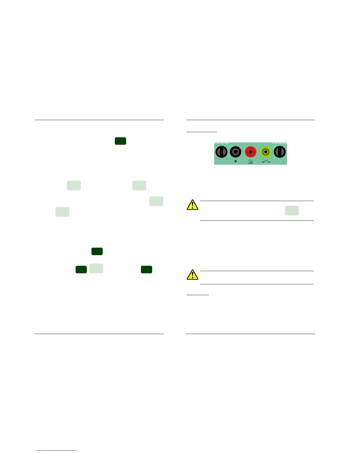
Monitor activation is signaled by a red LED labeled Monitor at the left edge
of Display #1. This takes place when –
a) some voltage within the 3 to 250 V AC or DC range drops be-
tween the BLACK / RED monitor taps, or
b) a dry contact (the most common case) closes between the BLACK /
GREEN monitor taps. This input is protected by a dedicated fuse
that will blow immediately if any voltage is applied.
REPLACE BLOWN FUSES WITH IDENTICAL ONES ONLY. DAMAGE
RESULTING FROM INCORRECT FUSE REPLACEMENT IS NOT COVERED
BY THE WARRANTY
Timer control
As commented above, the timer will start when you activate the power out-
put and will stop when the Monitor is activated. This is the timer’s default
start/stop mode, but you have more options that correspond to the various
combinations of the green event LEDs at the left of Display #1. To under-
stand timer modes, we need to distinguish between positive and negative
events:
RESET

 Loading...
