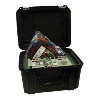
PTE-100-C
29
Activating the power output, closing a monitored contact or detect-
ing a voltage drop are positive events. Positive events are labeled
with an upward ( )arrow.
Automatic disconnection of the power output, opening a closed
contact of clearing an existing voltage at the monitor inputs are
negative events. These are labeled with a downward ( )arrow.
A wide choice of combinations between positive and negative events provide
great freedom to accommodate various test conditions and relay types by
selecting the class of event that must start or stop the instrument’s timer or
the power output. If, for example, the operation contact of the tested relay is
connected to a circuit under voltage, you can connect it in parallel to the
black and red monitor connectors and select a negative event for the timer’s
STOP mode, since any voltage present between these connectors will disap-
pear when the contact is closed upon relay’s operation.
You only need to press the button sequentially to toggle among the
timer’s various START/STOP event combinations.
Pulse Length Measurement
Timer start is usually associated with some action on the power output
switch, but an additional special mode allows the timer to be started and
stopped when monitor changes occur. This is the pulse length measurement
mode, with two options: positive and negative pulse. Select positive ( )
pulse to measure the time lapse between activation and deactivation of the
monitor. Select negative ( ) pulse to measure between the deactivation
and re-activation of the monitor.
Remember: monitor activation is signaled by the red LED labeled “Monitor”
on the left of Display #1.
SPECIAL MEASUREMENT AND CONTROL FUNCTIONS
A number of convenience features have been built into the PTE-100-C to
make its operation easier, sometimes saving the user from carrying addi-
tional instrumentation.
Access to these functions is located in a shaded area underneath Display
#1, which is used to view measured values and to enter control settings.
Mode
USER’S MANUAL
30
Press the button to toggle between Ch. (chrono) to Func. (function)
mode. The contents of Display #1 will change from timer readings to func-
tion-related readings and vice versa when you set back and forth from nor-
mal mode to function mode. Now, press the button briefly to navi-
gate sequentially throughout the functions list. The first 6 functions in the list
(from Vmon to S) are measurement functions, and the remaining 5 (from %
to Preset) are control functions, used to modify the default operation of some
PTE-100-C’s features.
Voltmeter and Frequency Meter
If you need to measure the voltage or the frequency of an external source
between 0 to 250 Vac or 250 Vdc, proceed as follows:
1) Enter the Func. Mode by pressing the button and press the
button repeatedly until the green LED near Vmon is lit.
2) Apply the voltage that you want to measure between the BLACK
and RED connectors of the Monitor Input. The value will be shown
in Display #1 with a “V” at its right edge, which will blink for DC
voltage.
3) If you are measuring AC, press once to jump to Fmon and
see the frequency in Hertzs.
If, rather than an external signal, you want to perform these measurements
on the unit’s AC supply line, press and hold the while in the above
mentioned functions until you heard a beep to activate (and further deacti-
vate) their secondary measurement mode.
Output Current-related Measurements
The injected current quantity is shown on the Display #2 during the tests, but
you can also obtain several useful measurements related to the connected
load and its nature on Display #1, such as applied voltage, impedance’s
modulus, impedance’s angle and apparent power.
Function

 Loading...