PTE-100-C
23
2. Connect the receptor’s input between the common (“0”) and the
current output tap that best accommodates the needed test range.
Always use the appropriate current range tap. This will keep distortion to a
minimum and will make regulation easier.
3. Use the button to identify the used tap to the instrument.
The PTE-100-C does not detect the current tap you are using, unless
you ‘flag’ it using the TAP button. Some measurement and protective
functions will not work if the green LED under the used tap is not lit.
4. Disconnect any unneeded cables from the unit.
5. Press briefly and release to ensure that current taps, rather
than voltage taps, are selected for display. The “A” indicator should
lit at the right edge of Display #2.
6. Press the button to switch the output on. Its red LED will lit
and some non-zero reading will be shown in Display #2, unless
you have left the output circuit open.
Display #2 needs about 2 seconds to stabilize itself. The decimal point will be
automatically placed to the biggest accuracy possible for the selected output.
All the power current and voltage outputs are energized when you
switch the injection ON, even though Display #2 shows ZERO.
Likewise, the voltage present in each tap depends directly on the
knob’s position. You cannot regulate each tap independently.
Regulate the injected current turning the variac knob gently while you ob-
serve Display #2.
If you want to use percentage regulation, set a nominal value in Display #1
using the “%” function and activate the percentage mode pressing .
If you want to know the voltage present at the selected current tap, activate
the Vtap function to have it shown on Display #1.
Enter/Print
ON
Out 1
Tap
USER’S MANUAL
24
If more than one current or voltage tap is connected to a receiver, the readings
at Display #2 will be meaningless.
Overload protection
If injected current exceeds by more than 10% the limit printed above the
used tap, the output will be stopped automatically. The ON/OFF LED will
then blink and the maximum output current value (or percentage) will be
held in Display #2. With the 100A/10V Current Tap, however, this protec-
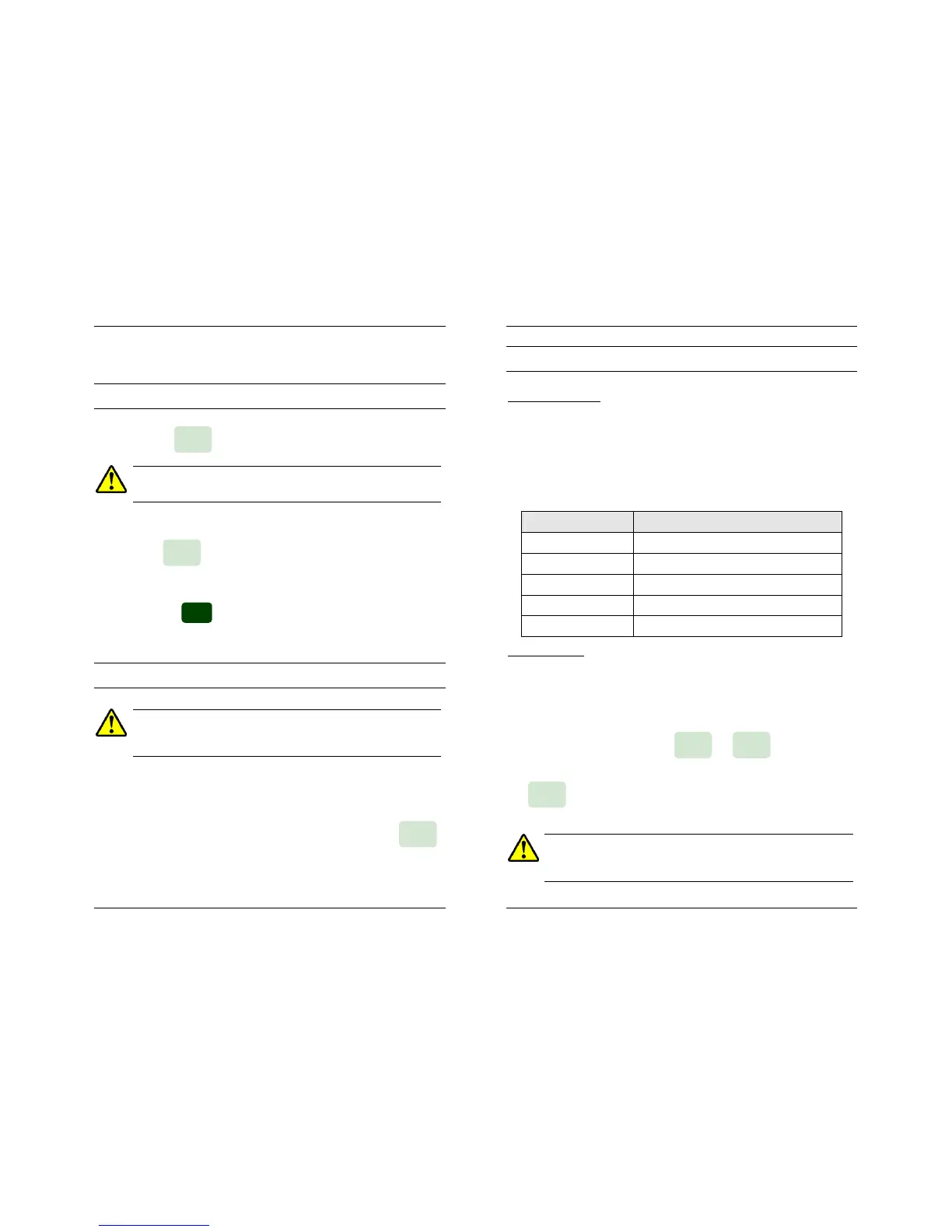
tion is timed inversely to the amount of excess, according to the table below.
Maximum current allowed through this tap is roughly 250 Amps.
Output Current Maximum Injection Time
<110A Until Thermal Overload Alarm Trips.
110 To 150A 10 Seconds.
150 To 210A 5 Seconds.
210 To 250A 3 Seconds.
>250A Immediate Trip by I lim Alarm.
Voltage Injection
The procedure is identical to current injection with only a few exceptions:
1. Connect your relay’s voltage input to Out 1 (AC voltage) or Out 2
(DC voltage) as required.
2. Have the appropriate tap (Out 1 or Out 2) shown in Display #2 by
pressing and holding the or buttons until you
hear a beep.
The button is irrelevant now because we are using the voltage out-
puts only.
All the power current and voltage outputs are energized when you
switch the injection ON, even though Display #2 shows ZERO.
Likewise, the voltage present in each tap depends directly on the
knob’s position. You cannot regulate each tap independently.
Tap
Out 2 Out 1

 Loading...
