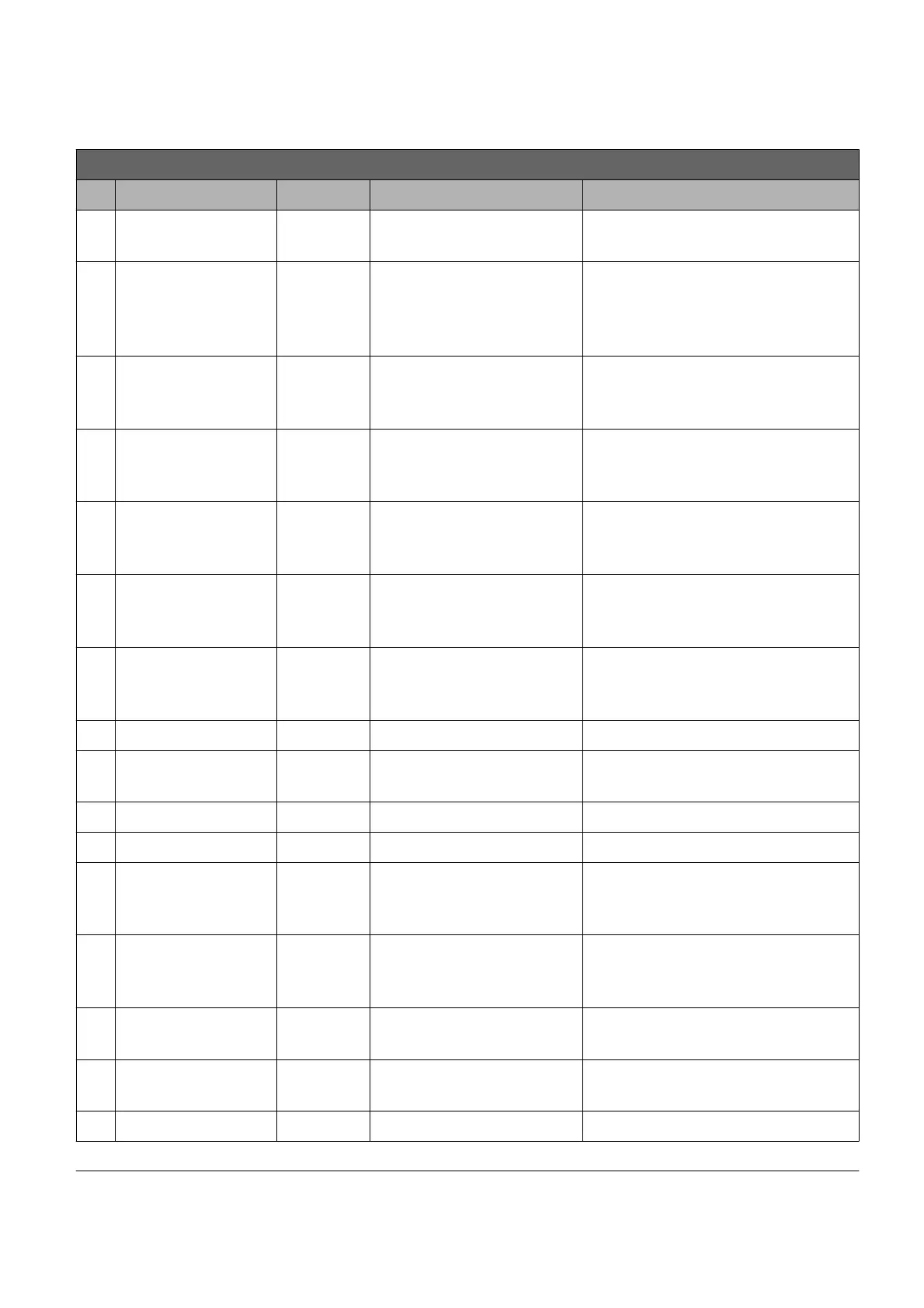
3.4.2 AC-M1 pin-out for DRIVE application
K1 connector pin-out for AC-M1 : DRIVE application
Pin Name I/O Specification Function
1 +KEY (B)
Supply
input
Rated battery +25/-30%,
6Amax
Positive supply of the control
section of the AC-M1
2 SEAT
digital
input
4mA pull-up,
VL<=1V,
VH>=3,5V
Safety contact signal; the safety
contact should be normally
open.
3 REVERSE
digital
input
4mA pull-up,
VL<=1V,
VH>=3,5V
Reverse direction selection
4
FORWARD
digital
input
4mA pull-up,
VL<=1V,
VH>=3,5V
Forward direction selection
5 START
digital
input
4mA pull-up,
VL<=1V,
VH>=3,5V
Throttle start selection
6
digital
input
4mA pull-up,
VL<=1V,
VH>=3,5V
Reserve
7
digital
input
4mA pull-up,
VL<=1V,
VH>=3,5V
Reserve
8 BUZZER output Low side 0,5A Buzzer command
9 COMMON
Positive
output
High side 5A max Positive common
10 RX Input Diagnosis interface
11 TX Out Diagnosis interface
12 PEDAL BRAKE
digital
input
4mA pull-up,
VL<=1V,
VH>=3,5V
Pedal brake request
13 PARK BRAKE
digital
input
4mA pull-up,
VL<=1V,
VH>=3,5V
Park brake request
14 LIN I/O 12mA pull-up
LIN display connection or LED
diagnosis
15 CAN-H I/O CAN-bus
H line input for CAN (No internal
termination resistor)
16 OUT3 output Low side 2A NEGATIVE BRAKE command
17 MAIN output Low side 1,5A Main contactor command
PRELIMINARY VERSION 17
 Loading...