ACX1_TAU_SYNC_UserManual_En
Page 31 of 37
SME S.p.A. Via della Tecnica 40 Z.I.
36071 ARZIGNANO (VI) ITALY
Phone +39 0444 470511 - Fax +39 0444 451803
sales@sme-group.com - www.sme-group.com
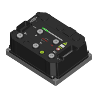
3.5.8 CAN Network
Serial Pins on Controller
Pin Meaning Pin Meaning
K3 - 2
CAN - L
K3 - 3 CAN - H
K3 - 3
CAN - L RES
K3 - 9 CAN - H RES
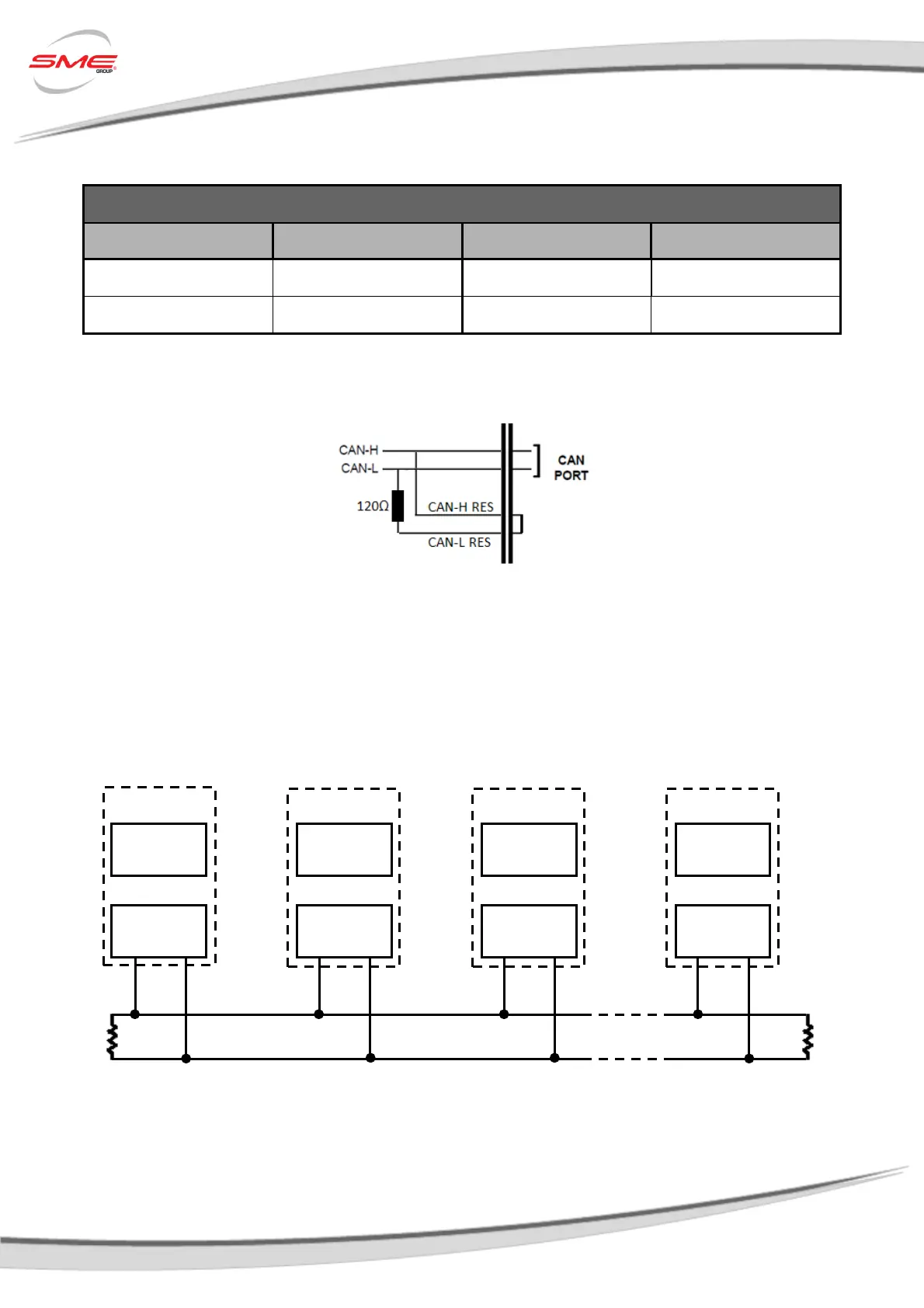
Wiring
Figure 136 - CAN Network Wiring
The High-Speed ISO 11898 Standard specifications are given for a maximum signaling rate of 1
Mbps with a bus length of 40m and a maximum of 30 nodes. It also recommends a maximum un-
terminated stub length of 0.3m. The cable is specified to be a shielded twisted-pair with a 120Ω
characteristics impedance (Z
0
). The Standard defines a single line of twisted-pair cable with the
network topology as shown in the following picture:
It’s terminated at both ends with 120Ω resistors in order to adapt the lines to a fixed impedance,
avoiding reflections or other problems that can occur at high frequency of CAN (from 125KBaud to
1Mb). Placing these resistors on a node should be avoided since the bus line loses termination if
the node is disconnected from the bus.
Node #1
CAN
Transceiver
CAN
Controller
CAN
Transceiver
CAN
Transceiver
CAN
Transceiver
CAN
Controller
CAN
Controller
CAN
Controller
 Loading...