ACX1_TAU_SYNC_UserManual_En
Page 9 of 37
SME S.p.A. Via della Tecnica 40 Z.I.
36071 ARZIGNANO (VI) ITALY
Phone +39 0444 470511 - Fax +39 0444 451803
sales@sme-group.com - www.sme-group.com
2.3.2 Signal: Inputs and Outputs
•
Digital Inputs: 9
•
Analog Inputs: 5
•
Digital Outputs (ON/OFF): 2
•
Driver Outputs (PWM): 4
•
Motor Speed/Position Sensor Inputs: 2 (A+B Channels/Sin+Cos Analog)
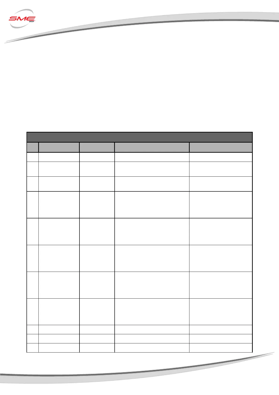
Refer to following tables for a complete AC-X1 controller K1 and K3 connectors pin-out.
K1 connector pin-out for AC-X1 SPECIFICATIONS
Pin Name I/O Specification Typical Function
1 GND I/O Ground Do not exceed 0.5A Negative Logic Supply
2 CAN-L CAN BUS CAN-BUS 1 MBit/s max
CAN L (No internal termination
resistor)
3 CAN-L RES CAN BUS
Connected to CAN-L with a series
120Ohm
Termination resistor
4 DIGITAL INPUT 1 Digital Input
VL<=2V,VH>=4.5V
Resistor pull-down(active high) or pull
up(active low)
ON rated voltage +12V/24V
TO BE ASSIGNED
5 DIGITAL INPUT 2 Digital Input
VL<=2V,VH>=4.5V
Resistor pull-down(active high) or pull
up(active low)
ON rated voltage +12V/24V
TO BE ASSIGNED
6 DIGITAL INPUT 3 Digital Input
VL<=2V,VH>=4.5V
Resistor pull-down(active high) or pull
up(active low)
ON rated voltage +12V/24V
TO BE ASSIGNED
7 DIGITAL INPUT 4 Digital Input
VL<=2V,VH>=4.5V
Resistor pull-down(active high) or pull
up(active low)
ON rated voltage +12V/24V
TO BE ASSIGNED
8 DIGITAL INPUT 5 Digital Input
VL<=2V,VH>=4.5V; resistor pull-
down(active high) or pull up(active
low)
ON rated voltage +12V/24V
TO BE ASSIGNED
9 I/O GROUND I/O Ground Do not exceed 0.5A Negative Logic Supply
10 +12V OUT Supply Output 12V ±5% 200mA 12V Supply
11 ANALOG INPUT 1 Analog Input 0÷12V 125KΩ pull-down TO BE ASSIGNED
 Loading...