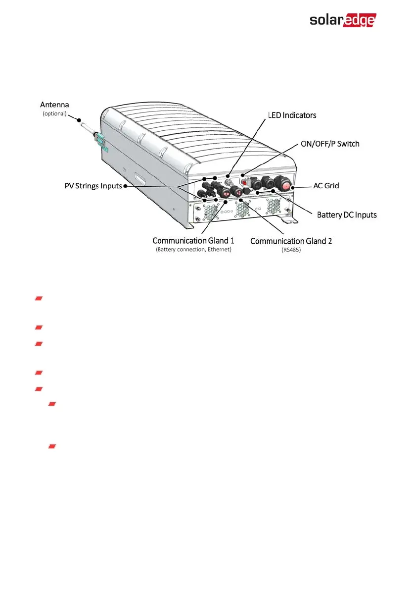
Inverter Interfaces
The following figure shows the inverter connectors and components, located at the
bottom of the inverter.
Figure 4: Inverter Interfaces
ACoutput: ACoutput gland, AC cable external gauge, M32 (15-21mm diameter) for
connection to the grid
DC input: MC4 connector, for connection of the PV installation.
Two communication glands: for connection of inverter communication options.
Each gland has three openings.
Battery DC inputs: Two battery glands for connecting charging cables (+ and -)
ON/OFF/P switch:
ON (1) - Turning this switch ON (after power optimizer pairing) starts the
operation of the power optimizers, enables power production and allows the
inverter to begin exporting power to the utility grid.
OFF (0) - Turning this switch OFF reduces the power optimizer voltage to a low
safety voltage and inhibits exportation of power. When this switch is OFF, the
control circuitry remains powered up.
StorEdge Three Phase Inverter MAN-01-00648-1.3
22 Inverter Interfaces
 Loading...