8 (E)
Chapter 1 Overview
This manual explains the location and function of parts
and controls of the BVM-D9H5U/D9H5E/D9H5A.
The explanation also applies to the optional BKM-
10R/11R Monitor Control Unit.
1 Tally lamp
With factory settings, the tally lamp lights as follows
when the pins of the PARALLEL REMOTE [1]
connector on the rear panel are shorted:
– in red, when pins No.3 and No.9 are shorted.
– in green, when pins No.4 and No.9 are shorted.
– in amber, when pins No.3, No.4 and No.9 are
shorted.
The tally lamp lights as follows when the pins of the
PARALLEL REMOTE [2] connector on the rear panel
are shorted:
– in red, when pins No.3 and No.5 are shorted.
– in green, when pins No.4 and No.5 are shorted.
– in amber, when pins No.3, No.4 and No.5 are
shorted.
By changing the setting in the REMOTE menu,
different pins on the remote connector can be used to
control the tally lamp.
For information about the REMOTE menu, see “[D]
Assigning the Remote Control Functions
— REMOTE Menu” on page 37(E).
2 STANDBY lamp
Lights when the monitor is in standby mode. The
monitor will be in standby mode under the following
conditions:
•The AC adaptor or battery is attached to the monitor
when the STANDBY MODE menu of the SYSTEM
CONFIG menu is set to ON.
•The monitor is changed from operation mode to
standby mode by external control.
For information about the SYSTEM CONFIG menu, see
“[E] Setting the Power-Up Conditions and Data about the
Screen Display — SYSTEM CONFIG Menu” on page
39(E).
3 POWER lamp
Lights when the monitor is put into operation mode
from standby mode (see STANDBY lamp 2) by
pressing the POWER switch 5.
Note
When the STANDBY lamp 2 is blinking, the monitor
cannot be put into operation mode (internal data
initialization is taking place). Wait until the
STANDBY lamp 2 is steadily lit.
4 DEGAUSS button
Press to degauss the CRT (every time the monitor is
turned on, the CRT is degaussed automatically). To
degauss again, wait for more than five minutes.
5 POWER switch
Press to turn on/off the monitor. By setting with the
ADDRESS menu, it is possible to turn on/off the
power of the specified monitors only, or of all
monitors at the same time.
For information about the ADDRESS menu, see “Selecting
the Monitor to Control — ADDRESS Menu” on page 45(E).
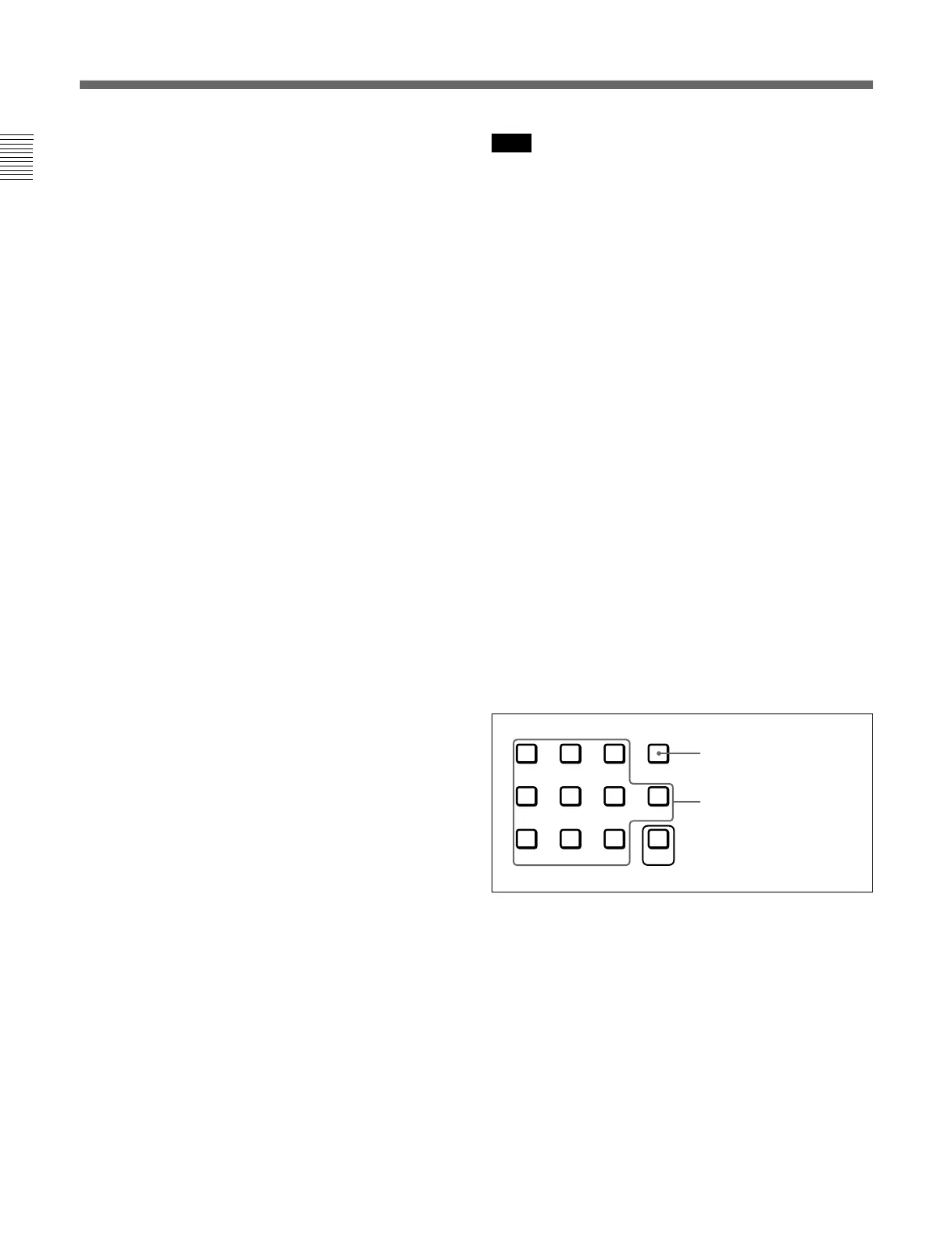
6 Ent button
Use to confirm the items, values and characters
entered.
7 Numeric keypad
Use to designate the channel number for the input
signal to be monitored, or to enter the setting values
with the menus.
8 Carrying handle
Pull out to use for carrying the monitor.
9 OPTION connector
Used to connect the BKM-11R Monitor Control Unit
or Auto Setup Probe (BKM-14L, etc.)
0 VOLUME control
Adjusts the volume of the audio signals from the
equipment connected to the AUDIO IN jacks at the
rear of the monitor.
Numeric buttons
Del button: Deletes the
values and characters
entered.
Location and Function of Parts
 Loading...