23 (E)
Chapter 1 Overview
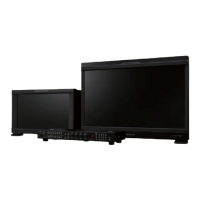
6 AC IN connector (3-pin)
Connects the monitor to an AC power source, via the
supplied AC power cord.
7 CONTROL UNIT connector (female, D-sub 9-
pin) (BVM-D14H1U/D14H1E/D14H1A only)
Connects a monitor control unit such as the BKM-10R
using a cable with D-sub 9-pin plugs such as an RCC-
5G (not supplied).
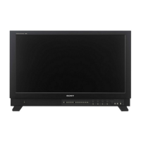
4 Analog input/output connectors (BKM-129X)
RGB signals or component signals (Y/PB/PR) can be
fed in the IN connectors. The type of signal applied to
each connector is set with the INPUT CONFIG menu.
The OUT connectors are used for loop-through output
of the input signal.
For information about the INPUT CONFIG menu, see “ [C]
Setting the Input Configuration — INPUT CONFIG Menu”
on page 35(E).
5 MAIN POWER switch
When turned on, the monitor enters operation mode.
By setting in the SYSTEM CONFIG menu, the
monitor can also be set to enter standby mode when
the MAIN POWER switch is turned on.
For information about the SYSTEM CONFIG menu, see “
[E] Setting the Power-Up Conditions and Data about the
Screen Display — SYSTEM CONFIG Menu” on page 39(E).
Attach the AC plug holder to the AC power cord, and
connect it to the AC IN connector so that the cord does not
come loose.
AC plug holder (supplied)
AC power cord
(supplied)
Y/G connectors (BNC)
PB/B connectors (BNC)
PR/R connectors (BNC)
SYNC connectors (BNC)
129X
IN
OUT
IN
OUT
IN
OUT
IN
OUT
ANALOG
Y/G
P
B
/B
P
R
/R
SYNC
 Loading...