Location and Function of Parts and Controls
13
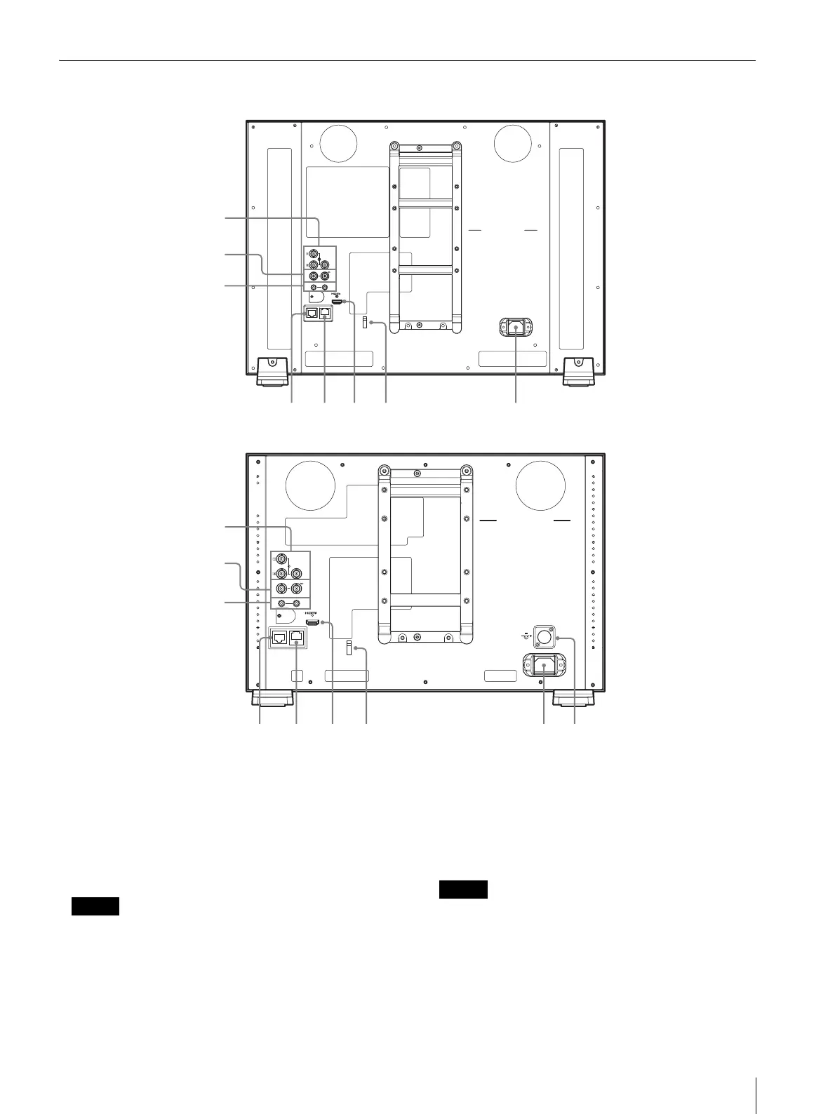
Rear Panel
a SDI (3G/HD/SD) input and output connectors
(BNC)
1 (input) connector, 2 (input) connector
Input connector for serial digital component signals.
SDI 1 and SDI 2 inputs are available.
OUT connector
Output connector for serial digital component signals.
Notes
• The signal from the OUT connector does not satisfy
the ON-LINE signal specifications.
• Output is only activated when the power is on. No
output in standby mode.
b COMPOSITE input and output connectors
(BNC)
IN connector
Input connector for composite video signals.
OUT connector
Loop-through output connector.
Note
When inputting a video signal with the jitters, etc. the
picture may be disturbed. We recommend using the
TBC (time base corrector).
c AUDIO input and output connectors (stereo
mini jack)
IN connector
SDI
OUT
OUTIN
COMPOSITE
OUT
IN
IN
AUDIO
PARALLEL
REMOTE
SERIAL
REMOTE
1
2
3
SDI
OUT
OUTIN
COMPOSITE
OUT
IN
IN
AUDIO
PAR AL LE L
REMOTE
SERIAL
REMOTE
1
2
3
PVM-2541A
PVM-1741A
 Loading...

