2-7
AC POWER
ADAPTOR
AC IN
VC-242D
Board
Cabinet (L) block assembly
Mechanism deck
Adjustment remote
commander (RM-95)
LANC jack
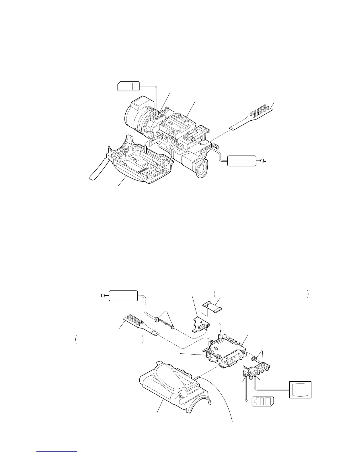
[MECHANISM DECK SERVICE POSITION-1]
[SERVICE POSITION TO CHECK THE VTR SECTION]
Note: Use the parts only which can be removed easily from outside of the mechanism deck.
CPC-13 jig
(J-6082-443-A)
Adjustment remote
commander (RM-95)
Control switch block (CF-4980) (14P)
(Connect here when cassette is going to be ejected.)
AC POWER
ADAPTOR
AC IN
DC-IN
connector (3P)
(1-794-637-11)
DD-138D board
Mechanism deck
VC-242D board
Cabinet (L) block assembly
JK-190 board
CPC-13 jig (J-6082-443-A)
Connect here when the tape path
check is going to be performed.
FP-191 flexible board (60P)
Insert the FP-191 flexible board in the opposite
direction to the normal insertion direction.
Monitor TV
LANC jack
VIDEO jack
Connection to Check the VTR Section
To check the VTR Section, set the VTR to the "forced VTR power ON" mode.
Operate the VTR functions using the adjustment remote commander (with the HOLD switch set in the OFF position)
(However, connect the cabinet (L) assembly when cassette is going to be ejected only.)
Setting the “Forced VTR Power ON” mode
1) Select page: 0, address: 01, and set data: 01.
2) Select page: D, address: 10, set data: 02, and press
the PAUSE button of the adjustment remote
commander.
Exiting the “Forced VTR Power ON” mode
1) Select page: 0, address: 01, and set data: 01.
2) Select page: D, address: 10, set data: 00, and press
the PAUSE button of the adjustment remote
commander.
3) Select page: 0, address: 01, and set data: 00.
 Loading...