EasyManuals Logo

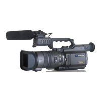
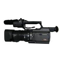
Sony DVCAM DSR-PD150 User Manual

Sony DVCAM DSR-PD150
141 pages
To Next Page IconTo Next Page
To Previous Page IconTo Previous Page
Page #55 background imageLoading...
Page #55 background image
2-9
LA-026
board
MS-049
Board
A
A
1
FP-190
flexible board (20P)
2
DC-IN connector (3P)
3
Battery terminal board (4P)
5
Screw (M2
×
5),
spring bolt
8
Screw (M2
×
5),
spring bolt
9
CPC cover
q;
Battery panel block assembly
4
Screw (M2
×
3),
spring bolt
6
Two screws
(M2
×
5),
spring bolt
7
Two screws
(M2
×
5),
spring bolt
1
Two tapping screws (B2
×
5)
8
Two tapping
screws (B2
×
5)
q;
Two tapping
screws (B2
×
5)
qa
DC jack retainer
qs
DC-IN connector
9
MS holder assembly
2
MK retainer
3
MK-014 board
When installing it,
align the switch position
as shown.
5
KP-010 board
7
MS-049 board
4
Screw (M2
×
3),
spring bolt
6
Two screws
(M2
×
3),
spring bolt
PRECAUTION DURING
INSTALLATION
2-9. BATTERY PANEL BLOCK ASSEMBLY (MK-014, KP-010, MS-049 BOARDS)
2-10.EVF BLOCK ASSEMBLY
L
A
-0
2
6
b
o
a
rd
2
Screw (M2
×
3),
spring bolt
6
Two screws
(M2
×
3),
spring bolt
7
EVF block assembly
3
Claw
5
Flexible clamp
4
Peel off the area
shown by shading.
1
FP-193
flexible board (27P)

Questions and Answers:

Question and Answer IconNeed help?

Do you have a question about the Sony DVCAM DSR-PD150 and is the answer not in the manual?

Sony DVCAM DSR-PD150 Specifications

General IconGeneral
BrandSony
ModelDVCAM DSR-PD150
CategoryCamcorder
LanguageEnglish

Related product manuals