EasyManuals Logo

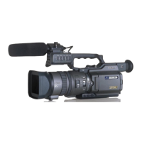
Sony DVCAM DSR-PD150 User Manual

Sony DVCAM DSR-PD150
141 pages
To Next Page IconTo Next Page
To Previous Page IconTo Previous Page
Page #54 background imageLoading...
Page #54 background image
2-8
2-7. CABINET (R) BLOCK ASSEMBLY
2-8. CABINET BOTTOM (D) ASSEMBLY
2
Four screws
(M2
×
5),
spring bolt
4
Two screws
(M2
×
5),
spring bolt
1
Two tapping screws
(B2
×
5)
3
Two tapping screws
(B2
×
5)
5
FBS cover
assembly
4
Cabinet (bottom)
3
Tripod table
5
Cabinet bottom
(D) assembly
1
FP-189
flexible board (6P)
2
FP-189
flexible board
REMOVING THE FBS COVER ASSEMBLY
CK-093
Board
1
Screw
(M2
×
5),
spring bolt
5
Screw
(M2
×
5),
spring bolt
4
Two screws
(M2
×
5),
spring bolt
6
Two screws
(M2
×
5),
spring bolt
7
Cabinet (R) block assembly
CK-093 board
3
CF ornamental plate
2
Claw
AC POWER
ADAPTOR
AC IN
Adjustment remote
commander (RM-95)
LANC
jack
[CK-093 BOARD SERVICE POSITION]
CPC-13 jig
(J-6082-443-A
)

Questions and Answers:

Question and Answer IconNeed help?

Do you have a question about the Sony DVCAM DSR-PD150 and is the answer not in the manual?

Sony DVCAM DSR-PD150 Specifications

General IconGeneral
BrandSony
ModelDVCAM DSR-PD150
CategoryCamcorder
LanguageEnglish

Related product manuals