VC-242D
Board
LA-026
Board
A
A
B
B
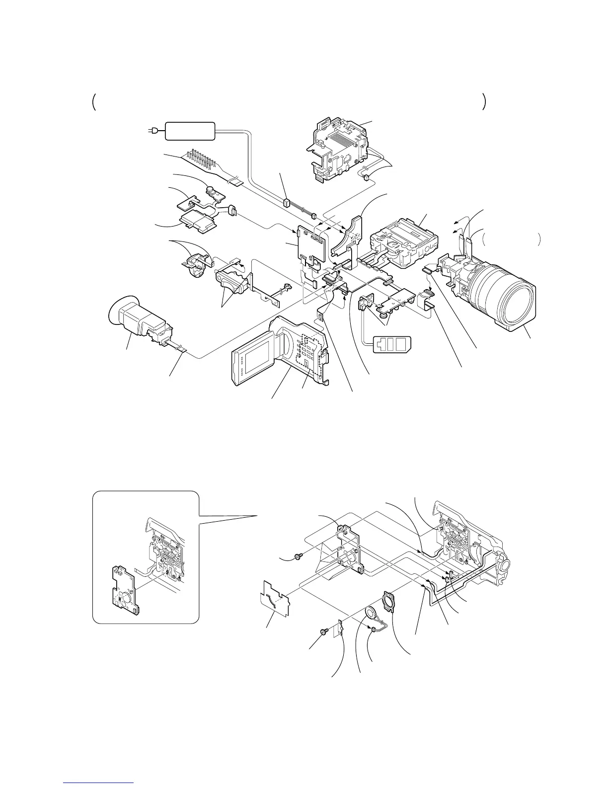
Adjustment remote
commander (RM-95)
AC POWER
ADAPTOR
AC IN
Cabinet (R) block assembly
CK-093 board
FP-187 flexible board (50P)
DC-IN
connector (3P)
(1-794-637-11)
Battery panel assembly
Battery terminal board (4P)
KP-010 board
MS-049 board
MK-014 board
EVF block assembly
FP-193
flexible board (27P)
Mechanism deck
DD-138D board
LA-026 board
VC-242D board
JK-190 board
CD-254 board (50P)
Extension cable
(J-6082-496-A) (50P)
Flexible board (39P)
from zoom lens
assembly
Flexible board (27P)
(from VAP assembly)
Lens block assembly
Control switch block
(PS-4980) (8P)
Control switch block
(CF-4980) (14P)
[CONNECTION DIAGRAM FOR SERVICE POSITION (Mainly for voltage measurement and check)]
CK-093, VC-242D, JK-190, CD-254, DD-138D, LA-026, KP-010, MK-014, MS-049 BOARDS,
MECHANISM DECK-2
CPC-13 jig
(J-6082-443-A)
1
Control switch block
(ED-4980) (6P)
2
FP-197 flexible board (6P)
9
FP-194 flexible board (5P)
3
R flexible
protection sheet
5
Two screws
(M2
×
3),
spring bolt
q;
Seven screws
(M2
×
3),
spring bolt
qa
Claw
6
SP retainer
plate assembly
4
Speaker (2P)
7
Speaker
8
Speaker holder
qd
Harness (CP-094) (14P)
qs
Harness (CP-093) (8P)
qf
CK-093 board
When installing it.
Align the switch position.
PRECAUTION DURING
INSTALLATION
 Loading...