EasyManua.ls Logo

Sony HCD-EC68 Service Manual

Sony HCD-EC68
62 pages
To Next Page IconTo Next Page
To Previous Page IconTo Previous Page
Page #26 background imageLoading...
Page #26 background image
HCD-EC68/EC78
HCD-EC68/EC78
2626
(2/2)
BOARD
K
MAIN
CN606
11
7.4
3.6
3.6
3.6
3.6
3.6
3.6
3.6
3.6
3.6
3.6
3.6
3.6
7.4
0.3 (5.2) 0 (0.2)
0.3 (5.2)
0.3 (5.2)
0.3 (5.2)
6
2
1
3
5
4
L501
BIAS OSC
S501
(REC/PB)
0
R515
100k
R511
100k
R513
150R509
1000p
C517
47p
C509
220p
C511
0
R516
100k
R512
150R510
100k
R514
220p
C512
47p
C510
47p
C525
47p
C526
2SC1740S-RT
Q501
2SC1740S-RT
Q502
2200p
C537
2200p
C536
2200p
C535
1
2
3
4
5
6
7
8
8P
CN501
9V
M-GND
SW
EH
VREF
Lch
COM
Rch
E
ET501
R540
47
R541
47
C539
1
R539 4.7
R537
10k
R538
10k
C538
0.01
R536
4.7k
R535 4.7k
R534
15k
R507
330k
R503
2.2k
C505
0.01
C503
2200p
C504
2200p
R504
2.2k
C506
0.01
R508
330k
2.2k
R501
2.2k
R502
16V
100
C502
16V
100
C501
R517
1k
R518
1k
C519
470p
C520
470p
C521
1
C522
1
R520
47k
R519
47k
R521
47k
R522
47k
C532
0.01
C531
0.01
R526
330k
R528
330k
R525
330k
R527
330k
R530
2.2k
R529
2.2k
R531
8.2k
R532
8.2k
C534
2200p
C533
2200p
50V
1
C513
50V
1
C514
TP501
TP502
TP504
TP503
TP505
TP506
TP508
TP509
TP507
C540
4700
16V47C516
16V47
C515
1000p
C543
25V
22
C542
100R543
100R544
0.1
C545
0.1C546
C527
470p
C528
470p
C530
330p
C529
330p
R523
3.3k
R524
3.3k
R505
15k
R506
15k
470
R545
470
R546
8765
4321
NJM4558V-TE2
IC502
GND
VCC
8765
4321
NJM4558V-TE2
IC501
GND
VCC
0.1
C524
0.1
C523
R533
22k
-
+
+
-
+
-
+
-
PB AMP
IC501
IC502
REC AMP
(CHASSIS)
DECK BOARD
REC-Rch
REC-Lch
I-TP-STATE
9V1
A-GND
9
M-GND
PB-Rch
9V
PB-Lch
Q501,502
OSC
TAP E
MECHANISM
DECK
PB
REC
-1
-2
7
D
B
69
F
53
G
1
C
E
H
84
A
2
E
B
E
B
18
Q501
Q502
L501
BIAS OSC
CN501
C501
C502
C513
C514
C515
C516
C540
C542
JW501
JW502
JW503
JW504
JW505
JW506
JW507
JW508
JW509
JW510
ET501
14
5
8
1
4
58
9
1
R501
R502
R503
R504
R505
R506
R507
R508
R509
R510
R511
R512
R513
R514
R515
R516
R517
R518
R519
R520
R521
R522
R523
R524
R525
R526
R527
R528
R529
R530
R531
R532
R533
R534
R535
R536
R537
R538
R539
C503
C504
R540
C505
R541
6
4
3
1
C506
R543
R544
R545
C509
R546
C510
C511
C512
C517
C519
C520
C521
C522
C523
C524
C525
C526
C527
C528
C529
C530
C531
C532
C533
C534
C535
C536
C537
C538
C539
C543
C545
C546
JR501
JR502
JR503
DECK BOARD
IC501
IC502
K
MAIN
BOARD
CN606
-2
-1
S501
S501
(REC/PB)
PB REC
TAPE
MECHANISM
DECK
1-875-501-
11
(11)
A
B
C
D
1234
(CHASSIS)
7-3. PRINTED WIRING BOARD - DECK Board (Except EC68: UK model) -
(Page
29)
• See page 23 for Circuit Boards Location.
: Uses unleaded solder.
7-4. SCHEMATIC DIAGRAM - DECK Board (Except EC68: UK model) -
• See page 37 for waveforms.
(Page 27)
w
w
w
.
x
i
a
o
y
u
1
6
3
.
c
o
m
Q
Q
3
7
6
3
1
5
1
5
0
9
9
2
8
9
4
2
9
8
T
E
L
1
3
9
4
2
2
9
6
5
1
3
9
9
2
8
9
4
2
9
8
0
5
1
5
1
3
6
7
3
Q
Q
TEL 13942296513 QQ 376315150 892498299
http://www.xiaoyu163.com
Question and Answer IconNeed help?

Do you have a question about the Sony HCD-EC68 and is the answer not in the manual?
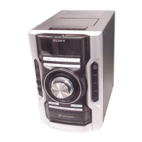
Sony HCD-EC68 Specifications

General IconGeneral
TypeMini Hi-Fi System
CD PlayerYes
CD ChangerNo
Tuner BandsFM/AM
USB PlaybackYes
Remote ControlYes
Speakers2
Weight (Main Unit)3.5 kg
BluetoothNo
Speaker Size10 cm
Weight (Speaker)2.5 kg

Summary

Service Manual Overview and Specifications

General System Specifications

Technical specifications for the HCD-EC68/EC78 audio system.

Amplifier Power Output

Details on power output ratings for various models and regions.

CD Player and Tuner Specifications

Specifications for the CD player and tuner sections.

Tape Deck Specifications

Details for the tape deck recording system.

Servicing, Disassembly, and Test Modes

Servicing Notes and Precautions

Important notes and precautions for servicing the unit.

Unit Disassembly Procedures

Detailed steps and flow for disassembling the unit.

Test Modes Overview

Various test modes for checking unit functions and performance.

Component Handling and Precautions

Optical Pickup and Laser Diode Handling

Precautions for handling the optical pickup block and laser diode safely.

Unleaded Solder Information

Information and characteristics of unleaded solder.

Disc Tray Lock Release

Procedure to release the disc tray lock mechanism.

Unit Maintenance Procedures

Opening the Disc Tray (Power Off)

Procedure to open the CD tray when the unit is off.

Removing the Volume Knob

Procedure for removing the volume knob.

Safety and Component Identification

Capacitor Discharge for Safety

Procedure to discharge capacitors on the main board for safety.

Tape Mechanism Deck Identification

Guide to differentiate between two types of tape mechanism decks.

Basic Unit Operations

Source Selection, Sound, and Playback

How to select sources, adjust sound, and play CDs/MP3s.

Initial Setup and Clock Setting

Initial setup instructions, including remote and clock settings.

Radio and Tape Playback

Guides for listening to radio and playing cassette tapes.

Display Information

How to change the information displayed on the system.

Advanced Operations and Timers

CD Programming and Tape Recording

How to create custom CD playback and record audio to tape.

Timer Functions

Explanation of the Sleep Timer and Play Timer functions.

Radio Station Presets

How to store and recall favorite radio stations.

Adjustments and Diagrams

Mechanical Adjustments

Procedures for adjusting mechanical parts like torque and tension.

Electrical Adjustments

Procedures for adjusting electrical components and heads.

Tuner Section Adjustments

Procedures for adjusting the tuner section's frequency and tracking.

Circuit Diagrams and Component Information

Diagram Interpretation Notes

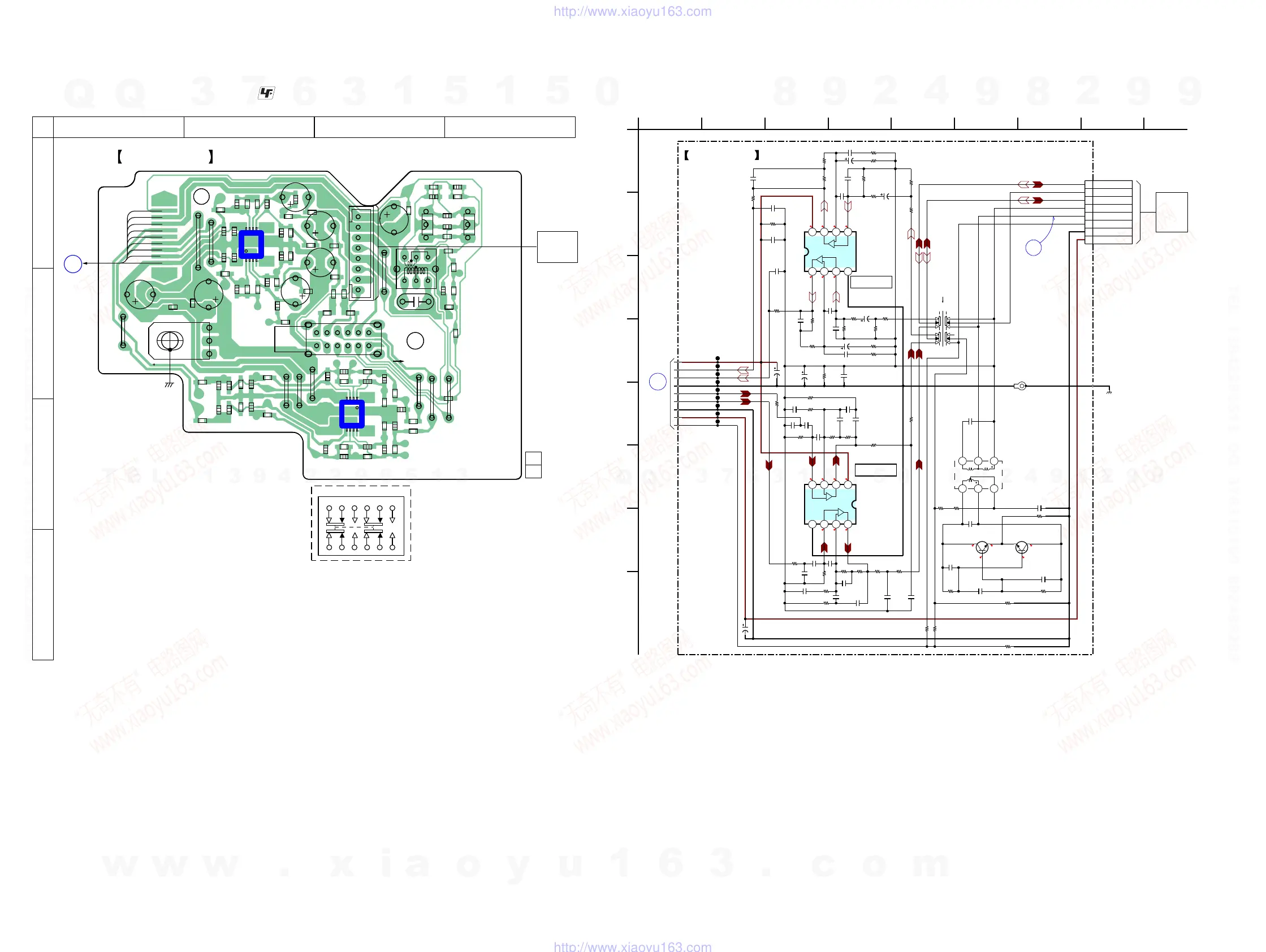
Notes on interpreting printed wiring board and schematic diagrams.

Circuit Diagrams and Layouts

Circuit diagrams and printed wiring board layouts for all sections.

Integrated Circuit (IC) Details

IC Block Diagrams

Block diagrams illustrating the function of key ICs.

IC Pin Function Descriptions

CD Board IC Pin Descriptions

Detailed pin functions for ICs on the CD board.

Panel Board IC Pin Descriptions

Panel Board IC301 Pinout

Pin description for IC301 on the Panel Board.

Other IC Pin Descriptions

IC601 Pin Description

Pin description for IC601.

Component Identification and Assembly

Exploded Views of Unit Sections

Visual breakdown of unit parts for identification and replacement.

Panel Section Exploded View

Exploded view of the panel section and its components.

Tape Deck Section Exploded View

Exploded view of the tape deck section.

Front Panel Section Exploded View

Exploded view of the front panel section.

Chassis and Main Section Exploded Views

Exploded views of the chassis and main sections.

CD Mechanism Section Exploded View

Exploded view of the CD mechanism section.

Electrical Parts List

Component Lists

Lists of capacitors, resistors, semiconductors, connectors, and ICs.

Related product manuals