B
A
L
(2/2)
CN607
BOARD
MAIN
BOARD
W401
KEY
POWER
CD
KEY
BOARD
31
32
(SUFFIX-12)
(SUFFIX-13)
(SUFFIX-12)
(SUFFIX-13)
1.3
3.1
1.3
0
3.3
2.9
3
1.5
3.3
3.3
0.9
3.3
3.3
0
3
2.8
1
3.3
3.3
1.3
3.1
3.1
0
3.3
0
0
3.1
0
0
1
1.4
3.1
0
0
0
0
0
3.3
0
0
3.1
3.1
3.1
3.1
3.1
1.3
1.3
1.3
1.3
1.3
1.3
2.6
0
0
0
3.1
3.1
3.1
0
3.9
0.7
8.1
4.5
0
0
0.7
0.1
5.7
0
3.1
3.3
3.9
7.5
4.94.9
4.8 4.8 4.8
4.94.9
0000
0
5.1
7.1
7.1
8.1 4.9
5.1
7.7
4.9
0
4.8
4.8 4.8 4.84.8
4.8 4.84.8 4.8
3.1
3.1
0 (1.3) <<3.1>> [0]
1.3
1.3
1.3
1.3
1.3
1.3
1.3
1.3
1.3
1.3
1.3
1.3
1.3
1.3
1.3
1.3
1.3
1.3
1.3
1.3
1.3
1.3
1.1
1.3
1.3
1.3
1.3
1.3
1.3
1.3
2SC3052F-T1-LF
Q304
2SC3052F-T1-LF
Q303
R332
10k
C301
0.1
2SC3052F-T1-LF
Q305
Q306
RT1N441C-TP-1
R337
220
R338
2.2
R339 2.2
R340
4.7k
R342
220k
C308
0.1
R343
470k
Q308
RT1N441C
Q310
2SC3052
C309
50V
22
R346
47k
R347
470
R354
47k
R348
47k
R349
470
R350
47k
R351
470
R352
47k
R353
470
R358
47k
R361
47k
R357 47k
R362
22k
R364
22k
R363
22k
R367
22k
R365
22k
C320 22p
C321
0.1
R327
100
R326
100
R325
10
Q301
2SC3052F-T1-LF
R328
10k
R381
10k
C313
0.22
R380
470
R384
10k
R383
10k
R402
100k
C338 1000p
100R301
R302 100
R303 100
R304 100
R305 100
R306 100
R307
100
R308
100
R309 100
R310 100
R312 100
R313 100
R314 100
R315 100
R316 100
R317 100
R318 100
R319 100
R320 100
R321 100
R322 100
R323
100
C310 0.1
C311
0.1
C312
0.1
C330 0.1
1L0341Y23E0CA602
LED301
Q309
KTA1273
R341
33k
Q317
2SC3440
Q315
2SC3440
Q318
2SC3440
Q316
2SC3440
Q313
2SA1365
Q311
2SA1365
Q314
2SA1365
Q312
2SA1365
KTA1271Y-AT
Q302
R334
10k
R331
100k
C302
10
50V
C341
0.1
R345
4.7k
R344
2.7k
R324 100
R333
100k
R336
10k
C305
10
50V
C303
10
50V
C317
1000p
R369
1k
R370
1k
R371
1k
R372
1k
R374
1k
R385
1k
R386
1k
R387
1k
27k
R419
100kR420
R390
10k
R392
10k
R389
*
R391
*
TP301
TP302
TP303
TP304
TP305
TP306
TP307
TP308
TP309
TP310
TP312
TP313
TP314
TP315
TP316
TP317
TP318
TP319
TP320
TP321
TP322
TP323
TP324
TP325
TP326
TP327
TP328
TP329
TP330
TP331
TP333
TP334
TP335
TP336
TP337
TP38
TP339
TP340
TP341
TP343
R329
2.2k
1
2
3
4
5
6
7
8
9
10
11
12
13
13P
CN302
M2-
M2+
M1-
M1+
SW-COM
SW3
SW1
I-CHACK
SW2
I-CLOSE
I-STOCK
I-OPEN
NC
R330
680
R421
10k
50V
C343
22
C314
0.047
C315
0.047
C316
0.047
C328
0.047
MAZ8043GMLS0
D301
R414
2.2k
R376
10k
R377
10k
R379
68k
R382
10k
4.7k
R422
C344
0.047
R335
22k
TP348
R368
10k
R426
100k
R366
10k
R428
47k
1.2k
R405
1.5k
R406
C345
0.047
R375
0
R373
0
1.2k
R412
1.5k
R413
R415
2.7k
R416
3.9k
R417
6.8k
R418
15k
0.047C346
Q307
ISA1235
C304
0.1
R360
1k
R359
1k
R356
1k
R355
1k
C306
6.3V
470
1
2
3
4
5
6
7
8
9
10
11
12
13
14
15
16
17
18
19
20
21
22
23
24
25
26
27
27P
CN304
R400 1k
R401 1k
C332 0.01
R378
33k
MC2836
D303
178910111256 14 19181713 16 2015 23
24 27
21
282625
22
31 33 3530 32 363429
234
37
LCD301
4.7k
R446
4.7k
R447
VCC
OUT
GND
NJL24H400B
IC302
1
3
2
MA2J1110GLS0
D305
MA2J1110GLS0
D302
MA2J1110GLS0
D304
FB301
C342
1000p
4700p
C354
4700p
C355
C356
0.1
32.768kHz
X301
C319
18p
R396
330k
S301
2
31
6MHz
X302
12345678
9101112131415161718192021222324252627282930
31
32 33
34 35 36
37
38 39
40
41
42
43
44
45 46
47
48
49 50
51 52 53 54 55 56 57
58 59 60 61 62 63 64 65 66 67 68 69 70 71 72
73 74 75 76 77 78 79 80
81
8283
84
8586
87
88
89
90
91
9293
94
9596
97
9899
100
MB90803PF-G-135E1
IC301
SEG32
O-AMP-ON
O-POWER
O-CD-ON
I-3CD-SW3/O-CDM-CLOSE
I-3CD-SW2/NC
I-3CD-SW1/O-CDM-OPEN
O-3CD-M1+/O-CDM-M1+
I-RMC
O-3CD-M1-/O-CDM-M1-
O-3CD-M2+/NC
O-3CD-M2-/NC
XOA
X1A
VCC
VSS
I/O-CD-BUS0
I/O-CD-BUS1
I/O-CD-BUS2
I/O-CD-BUS3
I-3CD-CHACK
I-3CD-STOCK
O-DR-MUTE
I-REQ
O-CD-BUCK
O-CD-CCE
O-CD-RST
O-LED-STBY
I-USB-TXD/
I-DMP-TXD
I-USB-DO/
I-DMP-5V-DET
O-USB-RXD/
O-DMP-RXD
AVC C
I-TU-DO
O-USB-DI/5V-ON/O-TP-REC-MUTE
AVS S
I-P-MONI
I-KEY1
I-KEY2
I-TU-ANSD
O-USB-SEL1_2/O-SW-ON/I-TP-STATE
I-KEY-WAKE-UP/VOL
I-HOLD
O-CD-SBSY
GND
I-DMP-DET/O-USB-RST
I-MODEL
I-SUFFIX
I-1CD-CLOSE_OPEN/NC
I/O-I2C-DATA
I/O-I2C-CLK
MD2
MD1
MD0
I-RST
O-TU-CE
O-TU-CLK
O-TU-DI
VLCD
COM0
COM1
CMO2
CMO3
SEG0
SEG1
VCC
VSS
SEG2
SEG3
SEG4
SEG5
SEG6
SEG7
SEG8
SEG9
SEG10
SEG11
SEG12
SEG13
SEG14
SEG15
SEG16
SEG17
SEG18
SEG19
SEG20
SEG21
SEG22
SEG23
SEG24
VCC
VSS
X1
X0
SEG25
SEG26
SEG27
SEG28
SEG29
SEG30
SEG31
C340 0.1
1
2
CN303
2P
KEY-1
GND
R425
0
1
2
2P
CN306
1
KEY-0
GND
I/O-BUS0
I/O-BUS1
I/O-BUS2
I/O-BUS3
O-CD-BUCK
O-CD-CCE
I-REQ
O-CD-SBSY
O-AMP-ON
O-DR-MUTE
O-POWER
I/O-I2C-CLK
I/O-I2C-DATA
I-TU-DO
I-TU-ANSD
O-TU-CLK
O-TU-DI
O-TU-CE
I-P-MONI
O-CD-RST
I-SW2
I-CHACK
I-SW1/CDM-OPEN
COM1
COM2
COM3
SEG0
SEG1
SEG2
SEG3
SEG4
SEG5
SEG6
SEG7
SEG8
SEG9
SEG10
SEG11
SEG12
SEG13
SEG14
SEG15
SEG16
SEG17
SEG18
SEG19
SEG20
SEG21
SEG22
SEG23
SEG24
SEG25
SEG26
SEG27
SEG28
SEG29
SEG30
SEG31
O-M2-
O-M2+
O-M1-/CDM-M-
I-HOLD
O-AMP-ON
O-CD-ON
O-M2-
LED-STBY
O-CD-BUCK
O-CD-CCE
M2+
M1-
I-REQ
O-DR-MUTE
SEG32
5V-ON/O-TP-REC-MUTE
SEG32
I-CLOSE/OPEN
I-CLOSE/OPEN
I-STOCK
O-CD-RST
I-RST
SEG15
SEG14
SEG13
SEG12
SEG11
SEG10
SEG9
SEG8
SEG7
SEG6
SEG5
SEG4
SEG3
SEG2
SEG1
SEG0
COM3
COM2
COM1
COM0
O-TU-CLK
O-TU-CE
SEG31
SEG30
SEG29
SEG28
SEG27
SEG26
SEG25
SEG16
SEG17
SEG18
SEG19
SEG20
SEG21
SEG22
SEG23
SEG24
5V-ON/O-TP-REC-MUTE
O-CD-SBSY
O-CD-ON
O-POWER
COM0
I-STOCK
I-CHACK
I/O-BUS0
I/O-BUS1
I/O-BUS2
I/O-BUS3
I-SW1/CDM-OPEN
O-M2+
I-RMC
I-SW2
LED-STBY
O-M1+/CDM-M+
O-SW-ON/I-TP-STATE
M1+
M1-
I-SW3/CDM-CLOSE
I-KEY-WAKE-UP/VOL
M2-
M1+
I-MODEL
I-SUFIX
I-RMC
I-TU-DO
I-KEY1
I-KEY2
I-TU-ANSD
I-KEY-WAKE-UP/VOL
I-HOLD
I-SUFIX
I-MODEL
I/O-I2C-DATA
I/O-I2C-CLK
I-SW3/CDM-CLOSE
M2+
O-TU-DI
I-RST
I-P-MONI
O-DMP-RXD
O-SW-ON/I-TP-STATE
M2-
I-KEY2
I-KEY1
REMOTE CONTROL
IC302
SW311SW312SW313SW314SW315SW316SW317SW318
SW319
DISPLAY
PANEL BOARD
SYSTEM CONTROLLER
IC301
LIQUID CRYSTAL DISPLAY
W301
O-TU-CE
O-TU-DI
O-TU-CLK
I-TU-ANSD
I-TU-DO
I/O-I2C-DATA
O-SW-ON/I-TP-STATE
I/O-I2C-CLK
5V-ON/TP-REC-MUTE
O-POWER
I-DMP-DET/O-USB-RST
O-CD-M-MUTE
O-AMP-ON
O-CD-SBSY
O-CD-REQ
O-CD-CCE
O-CD-BUCK
I/O-BUS3
O-CD-RST
I-P-MONI
O-CD-ON
D-GND
V-STBY
M-GND
I/O-BUS2
I/O-BUS1
I/O-BUS0
STANDBY
/
LED DRIVE
Q302-304
+4V REGULATOR
Q305,306
VOLTAGE DETECT
Q311-318
MOTOR DRIVE
*R389
27k (EC68: UK)
47k (EC68: AEP, RU, E2, E3, E51, MX, AR, AUS)
100k (EC78)
*R391
1k (EC68: AEP, UK, RU/EC78: AEP, RU)
2.2k (EC68: AUS)
5.6k (EC68: E3/EC78: E3)
100k (EC68: E51, MX, AR/EC78: E51, MX, AR)
47k (EC68: E2/EC78: E2)
EC78: RU, E2, E3, E51,
EC68: RU, E2, E3, E51,
MX, AR, AUS/
MX, AR
(EC68: UK)
(CHASSIS)
REGULATOR
Q307-310
CD
DECK
MECHANISM
RECEIVER
ROTARY ENCODER
VOLUME
-
TUNING +
SW305
FUNCTION
SW304
SW303
- TUNING
DSGX EQ
PLAY MODE
TUNING MODE
+
CD
711
D
B
1669 1710
F
5 15
L
K
3
G
1 12
C
E
H
8
J
4 13
A
142
I
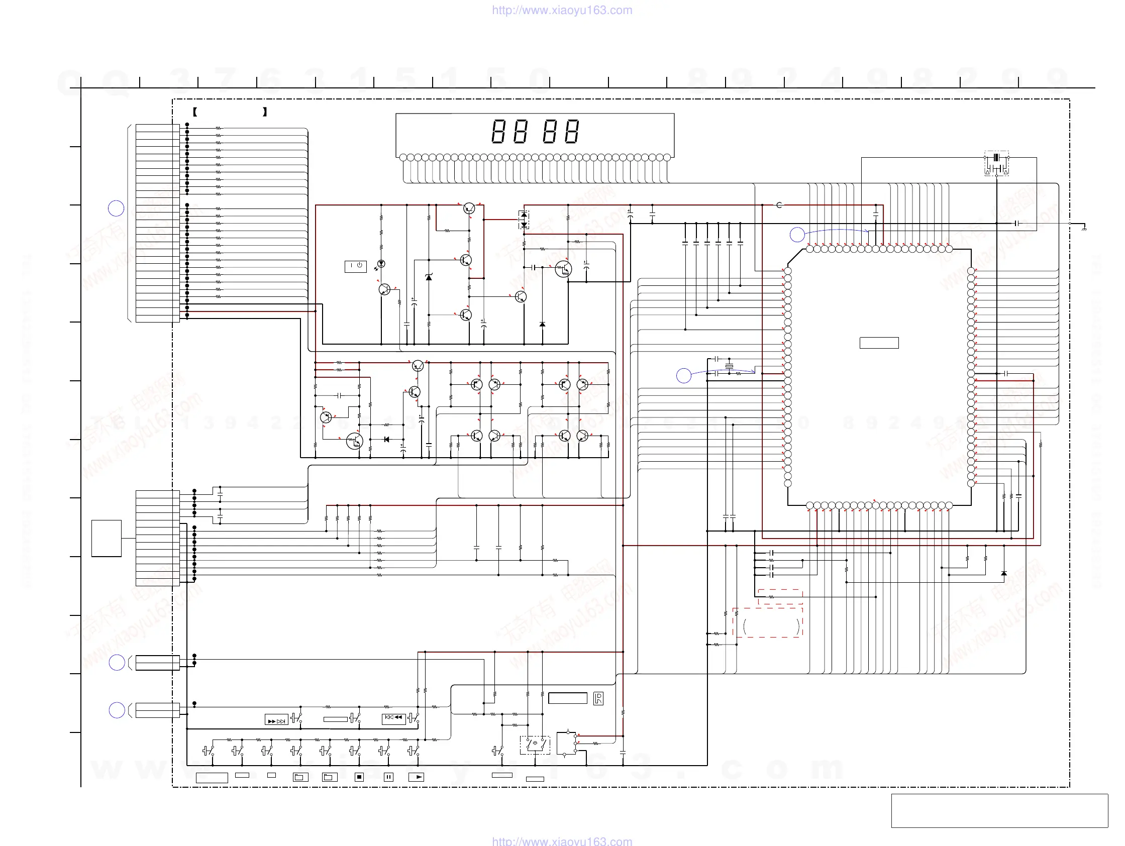
7-14. SCHEMATIC DIAGRAM - PANEL Board -
• See page 37 for waveforms. • See page 40 for IC Pin Function Description.
(Page 29)
(Page 34)
(Page 34)
Note: Refer to “SUFFIX-12/SUFFIX-13 DISCRIMINATION
OF PANEL BOARD” (page 3) of the servicing notes
for suffi x-12 and suffi x-13.
 Loading...