33
HCD-DFLX9W
SECTION 7
ELECTRICAL ADJUSTMENTS
0 dB=0.775 V
DECK SECTION
1. Demagnetize the record/playback head with a head
demagnetizer.
2. Do not use a magnetized screwdriver for the adjustments.
3. After the adjustments, apply suitable locking compound to the
parts adjust.
4. The adjustments should be performed with the rated power
supply voltage unless otherwise noted.
5. The adjustments should be performed in the order given in
this service manual. (As a general rule, playback circuit
adjustment should be completed before performing recording
circuit adjustment.)
6. The adjustments should be performed for both L-CH and R-
CH.
7. Switches and controls should be set as follows unless otherwise
specified.
• Test Tape
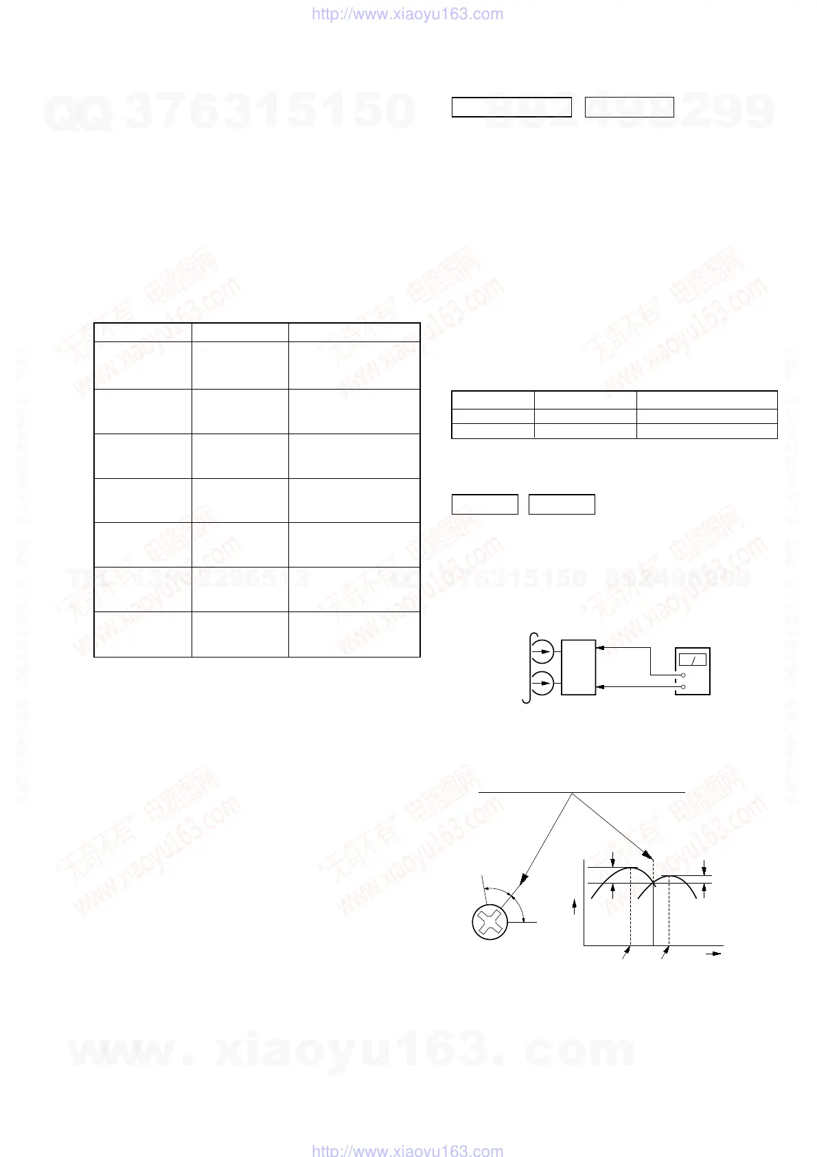
RECORD/PLAYBACK HEAD AZIMUTH ADJUSTMENT
DECK A DECK B
Note: Perform this adjustments for both decks
Procedure:
1. Mode: Playback
2. Turn the adjustment screw and check output peaks. If the peaks
do not match for L-CH and R-CH, turn the adjustment screw
so that outputs match within 1dB of peak.
set
SP RELAY board
CN804
Pin
2
(L-CH)
Pin
5
(R-CH)
SP RELAY board
CN804
Pin
3
(GND)
+
–
level meter
test tape
P-4-A100
(10 kHz, –10 dB)
Tape Signal Used for
P-4-A100 10 kHz, −10 dB Azimuth Adjustment
WS-48B 3 kHz, 0 dB Tape Speed Check
Screw
position
L-CH
peak
within
1dB
Output
level
L-CH
peak
R-CH
peak
within
1dB
Screw
position
R-CH
peak
Precaution
1. Clean the following parts with a denatured alcohol-moistened
swab:
record/playback heads pinch rollers
erase head rubber belts
capstan idlers
2. Demagnetize the record/playback head with a head
demagnetizer.
3. Do not use a magnetized screwdriver for the adjustments.
4. After the adjustments, apply suitable locking compound to
the parts adjusted.
5. The adjustments should be performed with the rated power
supply voltage unless otherwise noted.
Torque Measurement
3.06 N ⋅ m to 6.96 N ⋅ m
31 to 71 g ⋅ cm
(0.43 − 0.98 oz ⋅ inch)
0.19 N ⋅ m to 0.58 N ⋅ m
2 to 6 g ⋅ cm
(0.02 − 0.08 oz ⋅ inch)
3.06 N ⋅ m to 6.96 N ⋅ m
31 to 71 g ⋅ cm
(0.43 − 0.98 oz ⋅ inch)
0.19 N ⋅ m to 0.58 N ⋅ m
2 to 6 g ⋅ cm
(0.02 − 0.08 oz ⋅ inch)
6.96 N ⋅ m to 14.02 N ⋅ m
71 to 143 g ⋅ cm
(0.98 − 1.99 oz ⋅ inch)
9.80 N ⋅ m
100 g or more
(3.53 oz or more)
9.80 N ⋅ m
100 g or more
(3.53 oz or more)
Mode
Torque meter
CQ-102C
CQ-102C
CQ-102RC
CQ-102RC
CQ-201B
CQ-403A
CQ-403R
Meter reading
FWD
FWD
back tension
REV
REV
back tension
FF/REW
FWD tension
REV tension
SECTION 6
MECHANICAL ADJUSTMENTS
w
w
w
.
x
i
a
o
y
u
1
6
3
.
c
o
m
Q
Q
3
7
6
3
1
5
1
5
0
9
9
2
8
9
4
2
9
8
T
E
L
1
3
9
4
2
2
9
6
5
1
3
9
9
2
8
9
4
2
9
8
0
5
1
5
1
3
6
7
3
Q
Q
TEL 13942296513 QQ 376315150 892498299
TEL 13942296513 QQ 376315150 892498299
http://www.xiaoyu163.com
http://www.xiaoyu163.com
 Loading...