EasyManua.ls Logo

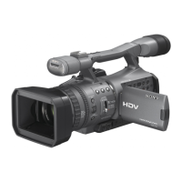
Sony HDR-FX7 User Manual

Sony HDR-FX7
117 pages
To Next Page IconTo Next Page
To Previous Page IconTo Previous Page
Page #40 background imageLoading...
Page #40 background image
3-8
HDR-FX7/FX7E_L2
3-8. OVERALL BLOCK DIAGRAM (8/8)
( ) : Number in parenthesis ( ) indicates the division number of schematic diagram where the component is located.
CN8203
KEY_AD2_7
SIRCS_SIG_FRONT
F_TALLY_LED
SIRCS_SIG_FRONT
F_TALLY_LED
SIRCS_SIG_REAR
XTALLY_LED_ONF_TALLY_LED
FOCUS
EXP.FOCUS
EXPOSURE KEY_AD7
KEY_AD0
KEY_AD4
AUTO_FOCUS
ASSIGN3
ASSIGN2
ASSIGN1
DIAL2_A_VM
DIAL2_B_VM
KEY_AD2_6
KEY_AD3_123 KEY_AD3
KEY_AD2
SIRCS_SIG_FRONT
KEY_AD3
KEY_AD2
KEY_AD3
KEY_AD2
GG-003 BOARD
(2/2)
FP-497
FLEXIBLE
BOARD
(2/2)
FP-492
FLEXIBLE
BOARD
(3/3)
FP-483 FLEXIBLE BOARD
REC
START/STOP
RUBBER TACT KEY
S303
(HANDLE ZOOM)
T
W
5
6
1
CN8205
(2/2)
2
1
RESET
S9601
OVERALL (5/8)
(PAGE 3-5)
26
OVERALL (4/8)
(PAGE 3-4)
24
OVERALL (1/8)
(PAGE 3-1)
1
OVERALL (4/8)
(PAGE 3-4)
18
OVERALL (6/8)
(PAGE 3-6)
30
OVERALL (3/8)
(PAGE 3-3)
14
FP-481 FLEXIBLE
BOARD
FP-498
FLEXIBLE
BOARD (2/2)
MM-061 BOARD (2/2)
4
REMOTE
SENSOR
(FRONT)
D101
REC LAMP
(FRONT)
IC101
CN8304
3
1
CN8202
(2/2)
1
2
3
4
CN8303
(2/2)
21
20
FP-484 FLEXIBLE
BOARD (2/2)
OO-003
BOARD
(3/3)
TT-003 BOARD (8/8)
4
REMOTE
SENSOR
(BACK)
D4002
REC LAMP
(BACK)
EXPOSURE
/IRIS DIAL
IC4001
CN6603
(2/2)
1
6
DISPLAY/
BATT INFO
S9602
XBATT_INFO_SW
XBATT_INFO_SW
PHOTO/
EXPANDED
FOCUS
S2001
S4001
PAUSE
X
STOP
x
REW
m
REC
z
PLAY
N
FF
M
SLOW
y
S9604
RV2001
(ZOOM)
W T
S001
(EJECT)
XEJECT_SW
PHOTO_REC
ZOOM_VR_AD ZOOM_SW_AD
SIRCS_SIG_REAR
SIRCS_SIG_FRONT
ZOOM_SW_AD
S1001
(REC START/STOP)
POWER
CAMERA
OFF (CHG)
VCR
CONTROL SWITCH BLOCK
(CK18500)
CONTROL SWITCH BLOCK (PS18500)
FP-485 FLEXIBLE BOARD
(2/2)
CONTROL SWITCH BLOCK (PL18500) (2/2)
CN1011
S3001 - S3004, S3006
1 2 3
ASSIGN
S3009
S3008
10
9
8
7
5
4
3
2
CN1008
(2/2)
15
CN502
6
XCAM_ON_SW
S/S
174
XVTR_ON_SW
XEJECT_SW
XCAM_ON_SW
XVTR_ON_SW
183
CN501
(2/2)
6
9
7
4
1
11
HI CONTROL
(16/18)
IC4001
139
140
141
KEY AD1
KEY AD0
KEY AD2
142
KEY AD3
143
KEY AD4
144
KEY AD6
KEY AD5
145
KEY AD7
137
KEY AD8
138
DIAL_A_VM
242
DIAL_B_VM
243
DIAL2_A_VM
244
DIAL2_B_VM
245
IC_4001_TXD0,
IC_4001_RXD0,
IC_4001_SCK0,
IC_4001_XCS0
IC3601
(3/3)
HI CONTROL
(12/18)
274
XHIDSCON_MAD
86
XHIDS_RST
XHIDS_RST
220
129
OSD_V
NTSC/XPAL_DET
A2
H7
A7
A8
B8
A6
NTSC/XPAL_DET
B1
XSYS_RST
NTSC/XPAL_DET
XSYS_RST
XSYS_RST
NTSC/XPAL_DET
XSYS_RST
B9
SYS_V SYS_V
G6
MULTI_JACK_AD
B4
XCHARGE_LED_ON
C9
XLANC_JACK_IN
MULTI_JACK_AD
XCHARGE_LED_ON
XLANC_JACK_IN
C2
B6
XCC_DOWN
B5
DCPACK_SW
275
XFUPSTAT
J8
H1
C8
D1, D2,
E1, E2
93 - 96
OFF
L
H
HOLD
(MANUAL)
AUTO_LOCK
S4008
SEL/
PUSH EXEC
CN6601
(2/2)
38
39
37
36
CN6602
(3/3)
38
36
37
39
41
CN1012
(3/3)
37
35
36
38
40
CN9602
CN9601
(3/3)
CN1007
(3/3)
KEY_AD6PANEL_OPEN
PANEL_REV
FP-494 FLEXIBLE
BOARD (3/3)
RR-003 BOARD (3/3)
S701
(PANEL REVERSE)
FP-487 FLEXIBLE BOARD
CONTROL SWITCH BLOCK (CF18500)
S702
(PANEL
OPEN/CLOSE)
424
415
KEY_AD5
442
KEY_AD8
433
KEY_AD1
3511
2719
XRESET XRESET
XRESET
LI_3V
2818
1
4
CN9603
WHT.BAL
LOCK
10
SHUT.SPEED
5
GAIN
4
MENU
11
EXEC
12
HOLD
2
3
P.PROFILE
STATUS
7
8
DIAL_A_VM
DIAL_B_VM
13
14
KEY_AD4_3
VOLUME/MEMORY
+
-
S9607 S9605
S4002, S4003, S4006, S4007
WHT BAL
SHUTTER SPEEDGAIN
MENU
PICTURE PROFILE
STATUS CHECK
S4004, S4005
S3005, S3007
EXPOSURE
/IRIS
PUSH
AUTO FOCUS
EXPANDED
FOCUS
FOCUS
S9608, S9610, S9612
S9614
54 6
PLAY INDEX DELETE
ASSIGN (CAMERA)
MEMORY(VCR)
S9603, S9606, S9609, S9611,
S9613, S9615, S9616
DIAL_A_VM
DIAL_B_VM
KEY_AD6
KEY_AD5
KEY_AD8
KEY_AD1
DIAL_A_VM
DIAL_B_VM
6
7
40
39
ZEBRA
70100 OFF
BT9601
LITHIUM
BATTERY
9, 10
37, 36
LED
DRIVE
Q4002
J5
J4
X4001
32.768 kHz
G1
G2
E8
E9
Q4001
LANC_IN
LANC_OUT
XLANC_PWR_ON
XLANC_ON
VTR_DD_ON
XCS_DD1
BATT_IN
IC4601
D_1.0V
D_2.8V, A_2.8V, D_2.5V
A_1.2V, D_1.2V, D_1.2V_K
ACV_UNREG
DC CONTROL,
RESET,
LANC DRIVER
(17/18)
K3
J3
J2
F3
F2
L3
M3
K13
D8
F9
C6
H2
N2A9
EVER_3.0V
MT_5V, EP_13V, D4_-2.8V, CMOS_-1.0V, DD_6.5V
D_1.8V
A_3.3V, D_3.3V
D_1.5V
BL_-15V
EP_8.5V
LANC_DC
VOUT
RP_4.6V, A_4.6V, AU_4.6V
D7
R1
P3
R2
M13, L13
C1, D3
LI_3V
CN4601
3
1
2
J1
LANC_SIG
LANC_SIG
D14
BL_CONT BL_CONT
N9
DD_SD1
XCC_DOWN
DD_SD1
ACV_UNREG
ACV_GND
BATT/XEXT
Q4604, Q4605
LF4601
INIT_CHARGE_ON
BATT_XEXT
CN4602
3
1
2
4
BATT_UNREG
DCPACK_SW
BATT_GND
BATT_SIG
BATT_SIG
FAST_CHARGE
Q4601, Q4602
Q4606, Q4607
Q4603
ACV_UNREG,
VTR_UNREG,
ST_UNREG
BATT_UNREG
+
BT901
BATTERY
TERMINAL
S
BATTERY
CHARGE
DETECT
DC IN
J901
C5, N12,
N5
FR_EVER_SO, FR_EVER_SCK
Question and Answer IconNeed help?

Do you have a question about the Sony HDR-FX7 and is the answer not in the manual?

Sony HDR-FX7 Specifications

General IconGeneral
Built-in displayYes
Display diagonal3.5 \
Display resolution (numeric)211000 pixels
Filter size62 mm
Digital zoom- x
Optical zoom20 x
Focal length range3.9 - 78 mm
Interchangeable lens-
Maximum aperture number2.8
Minimum aperture number1.6
Focal length (35mm film equivalent)37.4 - 748 mm
Maximum focal length (35mm film equiv)748 mm
Minimum focal length (35mm film equiv)37.4 mm
Sensor typeCMOS
Total megapixels1.07 MP
Optical sensor size1/4 \
Camcorder tape typeHDV
Camcorder media typeVideotape
Compatible memory cardsMS PRO
Internal storage capacity- GB
S-Video inNo
USB 2.0 ports quantity1
USB 3.2 Gen 1 (3.1 Gen 1) Type-A ports quantity0
Focus adjustmentAuto/Manual
Camera shutter speed1/3 - 1/10000 s
Camcorder typeShoulder camcorder
Minimum illumination4 lx
Supported aspect ratios4:3, 16:9
Product colorBlack
Maximum video resolution1920 x 1080 pixels
Image formats supportedJPG
Maximum image resolution1440 x 810 pixels
Audio systemstereo
Battery capacity- mAh
Battery life (max)8 h
Cables includedAV, USB
Aperture range (F-F)1.6 - 2.8
Weight and Dimensions IconWeight and Dimensions
Depth322 mm
Width145 mm
Height156 mm
Weight1400 g

Summary

Service Note

Power Supply During Repairs

Method for supplying power during repairs to prevent unit shutdown.

Forced Cassette Ejection

Procedure to manually eject a cassette when the unit does not eject.

Forced Power ON Mode Settings

Steps to enable forced camera and VTR power-on modes.

Using the Service Jig

Instructions for connecting and using the CPC-7 jig to the TT-003 board.

Self-Diagnosis Function

Overview and display of the unit's self-diagnosis system.

Shift Lens Error Troubleshooting

Troubleshooting steps for various shift lens errors identified by self-diagnosis codes.

Disassembly

Overall Disassembly Section 1

Exploded view and disassembly steps for the handle section.

Overall Disassembly Section 2

Exploded view and disassembly steps for the cabinet and mechanism deck.

Overall Disassembly Section 3

Exploded view and disassembly steps for BT, OO, and TT boards.

Lens Section Disassembly

Exploded view and disassembly steps for the lens unit.

Right Cabinet Section Disassembly

Exploded view and disassembly steps for the right cabinet components.

Left Cabinet Section Disassembly

Exploded view and disassembly steps for the left cabinet components.

Handle Section Disassembly

Exploded view and disassembly steps for the handle section components.

Lens Unit Disassembly Method

Detailed steps for safely disassembling the lens unit.

Block Diagrams

Overall Block Diagram (1/8)

First part of the overall system block diagram.

Overall Block Diagram (5/8)

Mid-point of the overall system block diagram.

Power Block Diagram (1/4)

First part of the power supply block diagram.

Power Block Diagram (4/4)

Final part of the power supply block diagram.

Printed Wiring Boards and Schematic Diagrams

Frame Schematic Diagrams

Overview of the main board and flexible board connections.

Schematic Diagrams Notes and Connections

General notes for schematic diagrams and connection diagrams.

Printed Wiring Boards

List of all printed wiring boards and their locations.

Mounted Parts Location - EE-006 Board

Component placement details for the EE-006 board.

Repair Parts List

Exploded Views Overview

Index of exploded views for all major sections of the camera.

Overall Section-1 Exploded View

Exploded view of the camera's main body and handle section.

Lens Section Exploded View

Exploded view of the camera's lens assembly.

Mechanism Deck Section Exploded View

Exploded view of the cassette loading and tape transport mechanism.

Electrical Parts List

List of electrical components with part numbers and specifications.
Related product manuals