 Loading...
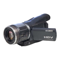
Do you have a question about the Sony HDR-FX7 and is the answer not in the manual?
| Built-in display | Yes |
|---|---|
| Display diagonal | 3.5 \ |
| Display resolution (numeric) | 211000 pixels |
| Filter size | 62 mm |
| Digital zoom | - x |
| Optical zoom | 20 x |
| Focal length range | 3.9 - 78 mm |
| Interchangeable lens | - |
| Maximum aperture number | 2.8 |
| Minimum aperture number | 1.6 |
| Focal length (35mm film equivalent) | 37.4 - 748 mm |
| Maximum focal length (35mm film equiv) | 748 mm |
| Minimum focal length (35mm film equiv) | 37.4 mm |
| Sensor type | CMOS |
| Total megapixels | 1.07 MP |
| Optical sensor size | 1/4 \ |
| Camcorder tape type | HDV |
| Camcorder media type | Videotape |
| Compatible memory cards | MS PRO |
| Internal storage capacity | - GB |
| S-Video in | No |
| USB 2.0 ports quantity | 1 |
| USB 3.2 Gen 1 (3.1 Gen 1) Type-A ports quantity | 0 |
| Focus adjustment | Auto/Manual |
| Camera shutter speed | 1/3 - 1/10000 s |
| Camcorder type | Shoulder camcorder |
| Minimum illumination | 4 lx |
| Supported aspect ratios | 4:3, 16:9 |
| Product color | Black |
| Maximum video resolution | 1920 x 1080 pixels |
| Image formats supported | JPG |
| Maximum image resolution | 1440 x 810 pixels |
| Audio system | stereo |
| Battery capacity | - mAh |
| Battery life (max) | 8 h |
| Cables included | AV, USB |
| Aperture range (F-F) | 1.6 - 2.8 |
| Depth | 322 mm |
|---|---|
| Width | 145 mm |
| Height | 156 mm |
| Weight | 1400 g |
Method for supplying power during repairs to prevent unit shutdown.
Procedure to manually eject a cassette when the unit does not eject.
Steps to enable forced camera and VTR power-on modes.
Instructions for connecting and using the CPC-7 jig to the TT-003 board.
Overview and display of the unit's self-diagnosis system.
Troubleshooting steps for various shift lens errors identified by self-diagnosis codes.
Exploded view and disassembly steps for the handle section.
Exploded view and disassembly steps for the cabinet and mechanism deck.
Exploded view and disassembly steps for BT, OO, and TT boards.
Exploded view and disassembly steps for the lens unit.
Exploded view and disassembly steps for the right cabinet components.
Exploded view and disassembly steps for the left cabinet components.
Exploded view and disassembly steps for the handle section components.
Detailed steps for safely disassembling the lens unit.
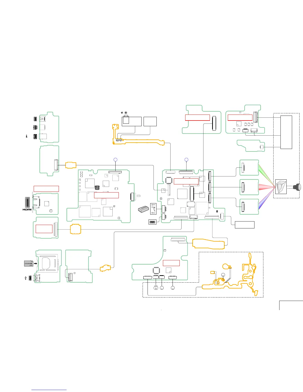
First part of the overall system block diagram.
Mid-point of the overall system block diagram.
First part of the power supply block diagram.
Final part of the power supply block diagram.
Overview of the main board and flexible board connections.
General notes for schematic diagrams and connection diagrams.
List of all printed wiring boards and their locations.
Component placement details for the EE-006 board.
Index of exploded views for all major sections of the camera.
Exploded view of the camera's main body and handle section.
Exploded view of the camera's lens assembly.
Exploded view of the cassette loading and tape transport mechanism.
List of electrical components with part numbers and specifications.