72
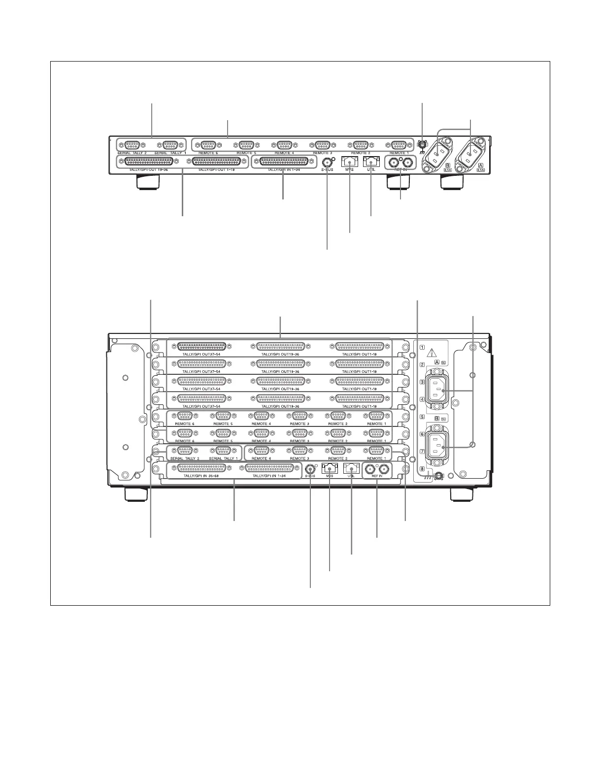
Rear view
a U (signal ground) terminal
Connect to the system ground.
b -AC IN (AC power input) A and B connectors
(3-pin)
Connect to 100 V to 240 V AC power supply with the
optional AC power cords.
The unit is equipped with two power supplies. When A or
B power supply is normal, unit operation can proceed.
c REF IN (reference video signal input) connectors
(BNC type)
Connect to an HD tri-level sync signal, black burst signal,
or analog sync signal when using the unit synchronized to
an external sync signal.
The two connectors are link through, so that the signal
input on either connector is also output on the other
connector. Connect the supplied 75 Ω terminator to the
remaining connector if not using the link through output.
a U terminal
f S-BUS connector
e MVS connector
c REF IN connectorsh SERIAL TALLY 1 and 2 connectors
MKS-X7700
a U terminal
b -AC IN A and B
connectors
f S-BUS connector
d UTIL connector
e MVS connector
c REF IN connectors
MKS-X2700
j TALLY/GPI IN 1 to 68 connectors
h SERIAL TALLY 1 and 2 connectors
g REMOTE 1 to 6 connectors
j TALLY/GPI IN 1 to 34 connectors
b - AC IN A and B
connectors
i TALLY/GPI OUT 1 to 36 connectors
d UTIL connector
i TALLY/GPI OUT 1 to 54 connectors
(when MKS-X7701 is installed)
g REMOTE 1 to 6 connectors
(when MKS-X7702 is installed)
g REMOTE 1 to 4 connectors
 Loading...


