3
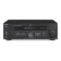
STR-DE400
TABLE OF CONTENTS
1. GENERAL ................................................................... 4
2. TEST MODE ............................................................... 10
3. DIAGRAMS
3-1. Block Diagram – MAIN Section –.................................. 14
3-2. Block Diagram – DISPLAY/POWER Section – ............. 15
3-3. Printed Wiring Board – DIGITAL Board (Side A) –...... 16
3-4. Printed Wiring Board – DIGITAL Board (Side B) –...... 17
3-5. Schematic Diagram – DIGITAL Board (1/3) – .............. 18
3-6. Schematic Diagram – DIGITAL Board (2/3) – .............. 19
3-7. Schematic Diagram – DIGITAL Board (3/3) – .............. 20
3-8. Printed Wiring Board – MAIN Board – ......................... 21
3-9. Schematic Diagram – MAIN Board (1/3) – ................... 22
3-10. Schematic Diagram – MAIN Board (2/3),
HEADPHONE Board – ................................................... 23
3-11. Schematic Diagram – MAIN Board (3/3),
ADCC Board, STANDBY Board – ................................. 24
3-12. Printed Wiring Boards
– ADCC Board, HEADPHONE Board – ........................ 25
3-13. Printed Wiring Board – STANDBY Board – ................. 26
3-14. Printed Wiring Board – DISPLAY Board – ................... 27
3-15. Printed Wiring Boards
– TUNING Board, POWER Board – .............................. 28
3-16. Schematic Diagram – DISPLAY Board,
TUNING Board, POWER Board – ................................. 29
3-17. Printed Wiring Board – VIDEO Board –........................ 30
3-18. Schematic Diagram – VIDEO Board – .......................... 31
4. EXPLODED VIEWS
4-1. Front Panel Section ......................................................... 39
4-2. Chassis Section................................................................ 40
5. ELECTRICAL PARTS LIST .................................. 41
SERVICING NOTE
Note on replacement POWER AMPLIFIER IC
There are two kinds of sets by POWER AMPLIFIER IC (IC501,
IC601, IC701: on MAIN board) used with this model.
Type1 : 6-600-450-01 IC STK350-530-E
Type2 : 6-710-828-01 IC STK350-530T-E
Ref. No. Type1 : STK350-530-E Type2 : STK350-530T-E
Wiring Board
Location
C504 1-102-233-00 CERAMIC 33PF 10% 500V 1-101-810-00 CERAMIC 100PF 5% 500V D-6
C554 1-102-233-00 CERAMIC 33PF 10% 500V 1-101-810-00 CERAMIC 100PF 5% 500V D-7
C604 1-102-233-00 CERAMIC 33PF 10% 500V 1-101-810-00 CERAMIC 100PF 5% 500V D-7
C654 1-102-233-00 CERAMIC 33PF 10% 500V 1-101-810-00 CERAMIC 100PF 5% 500V D-8
C704 1-102-233-00 CERAMIC 33PF 10% 500V 1-101-810-00 CERAMIC 100PF 5% 500V F-3
IC501 6-600-450-01 IC STK350-530-E 6-710-828-01 IC STK350-530T-E E-6
IC601 6-600-450-01 IC STK350-530-E 6-710-828-01 IC STK350-530T-E E-8
IC701 6-600-450-01 IC STK350-530-E 6-710-828-01 IC STK350-530T-E F-3
As for the set of type1 and type2, the parts on the Main board in the
table below are different.
When repairing, please confirm the type name printed on IC at the
beggining and use the parts corresponded to the table below.
Ver. 1.2
 Loading...