EasyManua.ls Logo

Sony STR-DE400 Service Manual

Sony STR-DE400
52 pages
To Next Page IconTo Next Page
To Previous Page IconTo Previous Page
Page #35 background imageLoading...
Page #35 background image
35
STR-DE400
IC203 NJM2279D
1
3
V1
2
S1
13
S1
8
+5V
911
M
10
MON
5
VOUT
6
GND
4
S2
7
GND
14
-5V
V2
V3
12
75
4.45k
4.14k
75Driver
6.3dB
6dB Amp
20k
20k
75
4.45k
4.14k
75Driver
6.3dB
6dB Amp
20k
20k
20k
DISPLAY Board
IC100 PT6315
1
2
3
4
5
4-bit latch
24-bit output latch
12-bit shift register
Data selector
6
7
8
9
10
11
12 13 14 15 16 17 18 19 20 21 22
23
24
25
26
27
28
29
30
31
32
33
3435363738
Serial
interface
OSC
Timing generator
key scan
Display memory
24 bits x 12 words
Key data memory
(2 x 16 bits)
Command decoder
segment driver
Grid driver
Multiplexed driver
394041424344
LED1
LED2
LED3
LED4
OSC
DOUT
DIN
CLK
STB
KEY1
KEY2
VSS
VDD
SEG1/KS1
SEG2/KS2
SEG3/KS3
SEG4/KS4
SEG5/KS5
SEG6/KS6
SEG7/KS7
SEG8/KS8
SEG9/KS9
SEG10/KS10
SEG20/GRID9
SEG21/GRID8
SEG22/GRID7
SEG23/GRID6
SEG24/GRID5
GRID4
GRID3
GRID2
GRID1
VDD
VSS
SEG11/KS11
SEG12/KS12
SEG13/KS13
SEG14/KS14
SEG15/KS15
SEG16/KS16
VEE
SEG17/GRID12
SEG18/GRID11
SEG19/GRID10
VIDEO Board

Other manuals for Sony STR-DE400

Question and Answer IconNeed help?

Do you have a question about the Sony STR-DE400 and is the answer not in the manual?
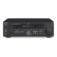
Sony STR-DE400 Specifications

General IconGeneral
TypeAV receiver
Number of Channels5.1
Total Harmonic Distortion (THD)0.09 %
Impedance8 Ohms
Outputs1 Audio, 1 Video

Summary

Specifications Overview

Amplifier Power Output Specifications

Details power output for various regions and conditions.

Electrical Performance Parameters

Covers frequency response, input/output details, and gain levels.

Tuner, Video, Power, and General Specifications

FM/AM Tuner and Video Performance

Details performance parameters for FM/AM tuners and video inputs/outputs.

Power Consumption, Dimensions, and Requirements

Lists power usage, physical specs, and general requirements.

Important Notes and Safety Information

Covers component replacement, safety precautions, and model identification.

Diagrams and Schematics

Block Diagrams

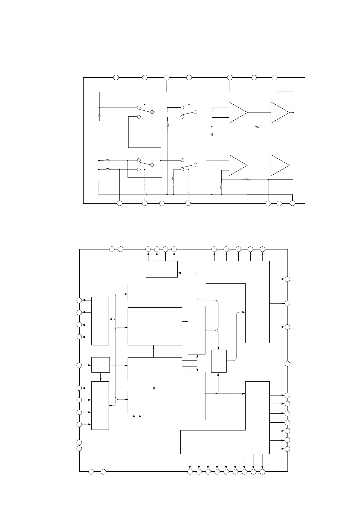
Presents block diagrams for main and display/power sections.

Printed Wiring Boards (PWBs)

Covers PWBs for digital, main, ADCC, headphone, standby, display, tuning, power, video boards.

Schematic Diagrams

Covers schematics for digital, main, headphone, ADCC, standby, display, tuning, power, video boards.

Circuit Board Locations and Waveforms

Shows board layout and digital board waveform examples.

General Information and Controls

Front Panel Controls Overview

Describes the function of each button and jack on the front panel.

Front Panel Display Indicators

Describes indicators for signal input, processing, system status, and channels.

Rear Panel Connections

Digital and Audio Input/Output Ports

Details digital, audio, and component video connection sections.

Antenna, Speaker, and Video Ports

Covers antenna, speaker, and video/audio output connections.

Remote Commander Operation

Basic Power and Input Control Functions

Explains power on/off and input selection functions.

Menu Navigation and Sound Field Selection

Describes how to access menus and select sound fields.

Remote Functions and Features

Details tuning, navigation, volume, muting, and channel controls.

Mode Selection and Calibration Functions

Covers 2CH stereo, A.F.D. mode, auto calibration, and TV/VIDEO input selection.

Test Modes

Preset and Channel Step Modes

Describes factory preset and AM channel step selection modes.

Indicator, Version, and Key Check Modes

Covers fluorescent indicator test, software version, and key check modes.

Shipment, Protector, and Decode Modes

Details shipment, protector, and auto decode test modes.

Advanced Test Modes

Swap All Mode and ADCC Test Stages

Explains swap all mode and the stages of ADCC factory test.

ADCC DSP Data Line and Auto Cal MIC Checks

Details the specific checks within the ADCC factory test mode.

Diagram Reading Conventions

Schematic Diagram Notations

Explains symbols and abbreviations used in schematic diagrams.

Printed Wiring Board Notations

Details symbols and abbreviations for printed wiring boards.

Exploded Views

Front Panel Assembly Parts

Shows the parts breakdown of the front panel assembly.

Chassis Assembly Parts

Shows the parts breakdown of the chassis assembly.

Electrical Parts List

ADCC and Digital Board Components

Lists components for ADCC and Digital boards.

Main Board Components

Lists components for the Main board.

Headphone Board Components

Lists components for the Headphone board.

Video, Tuning, Power, and Standby Board Components

Lists components for Video, Tuning, Power, and Standby boards.

Related product manuals