 Loading...
Do you have a question about the Sony STR-DH510 and is the answer not in the manual?
| AirPlay | No |
|---|---|
| Display | VFL |
| Equalizer | Yes |
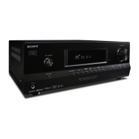
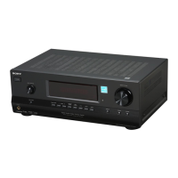
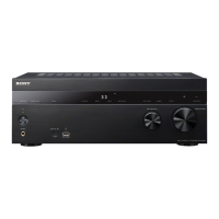
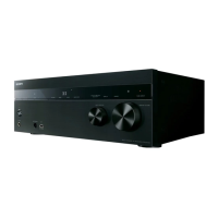
| Product color | Black |
| Audio decoders | Dolby Digital, Dolby Pro Logic II, dts |
| Apple docking compatibility | Not supported |
| Impedance | 8 Ω |
| Receiver type | Surround |
| Frequency range | 20 - 20000 Hz |
| RMS rated power | 500 W |
| Audio output channels | 5.1 channels |
| Total Harmonic Distortion (THD) | 1 % |
| Power output per channel (20-20KHz@8 Ohm) | 100 W |
| HDMI in | 3 |
| Digital audio optical in | 1 |
| Component video (YPbPr/YCbCr) in | 2 |
| Connectivity technology | Wired |
| Speakers connectivity type | - |
| Headphone connectivity | 3.5 mm |
| AM band range | 530 - 1710 kHz |
| FM band range | 87.5 - 108 MHz |
| Supported radio bands | AM, FM |
| Power consumption (standby) | 0.3 W |
| Power consumption (typical) | 230 W |
| Depth | 322 mm |
|---|---|
| Width | 430 mm |
| Height | 157.5 mm |
| Weight | 7400 g |
Details output power and total harmonic distortion for US models.
Procedure for testing AC leakage current from exposed metal parts to earth ground.
Characteristics and guidelines for using unleaded solder in assembly.
Warning to replace components marked ▲ with specific Sony parts for safety.
Step-by-step instructions for disassembling the unit, starting with the case.
Guide to various test modes for checking functions and initializing settings.
Procedure to verify the FM tuner's auto-stop scanning functionality.
Block diagrams for Tuner/Audio, Video Standby, HDMI PC, Key/Display, Power Key sections.
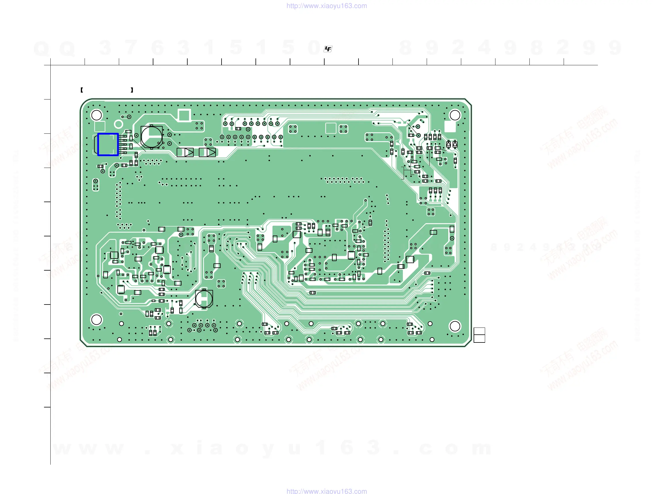
Schematics and printed wiring boards for the main board sections.
Printed wiring boards and schematics for the digital board sections.
Diagrams for video standby and HDMI PC boards, including schematics and PWBs.
Exploded view of the unit's case with part numbers and references.
Exploded view and list of components for the front panel.
Comprehensive list of capacitors, including part numbers and specifications.
Detailed pin functions and descriptions for IC2001 on the digital board.
Detailed pin functions for IC2101, the system control IC.