8 Power supply
Six different sources can provide the power supply to NUCLEO-H563ZI:
• A host PC connected to CN1 through a USB cable (default configuration)
• An external 7 to 12 V power supply connected to CN8 pin 15 or CN11 pin 24 (VIN)
• An external 5 V power supply connected to CN11 pin 6 (5V_EXT)
• An external 5 V USB charger (VBUS_STLK) connected to CN1
• A host PC connected to CN13 through a USB cable
• An external 3.3 V power supply (3V3) connected to CN8 pin 7 or CN11 pin 16
In case VIN, 5V_EXT, or 3V3 is used to power the STM32H5 Nucleo-144 board, this power source must comply
with the EN-60950-1: 2006+A11/2009 standard and must be safety extra low voltage (SELV) with limited power
capability.
In case the power supply is +3.3 V, STLINK-V3EC is not powered and cannot be used.
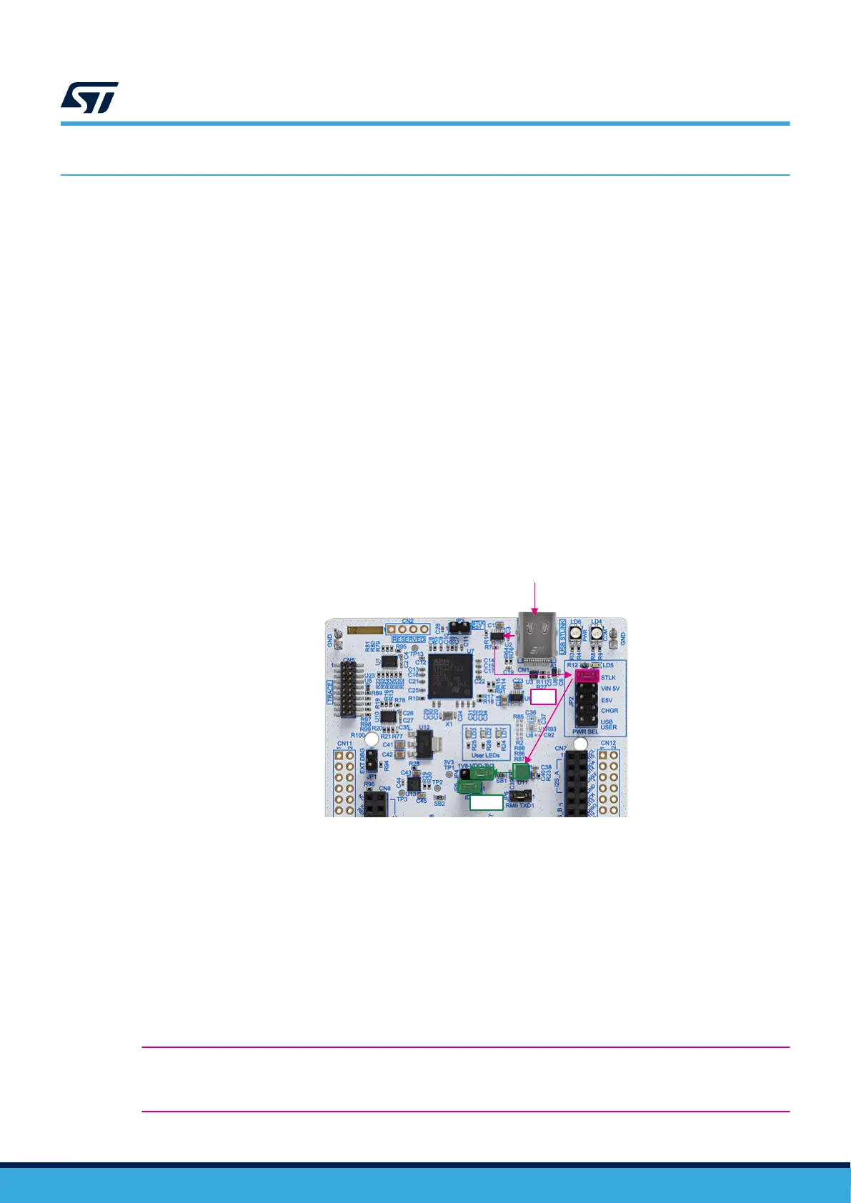
8.1 Power supply input from STLINK-V3EC USB connector: 5V_STLK (default
configuration)
The 5 V signal on the STLINK-V3EC USB connector (CN1) can power the STM32H5 Nucleo-144 board and its
shield. To select the 5V_STLK power source, JP2 must be set on [1-2] ‘STLK’ (refer to Figure 8).
This is the default configuration.
Figure 8. Power supply input from STLINK-V3EC USB connector with PC (5 V, 500 mA maximum)
DT59064V1
PC
5V
5V
3V3
If the USB enumeration succeeds, the ST-LINK power is enabled, by asserting the T_PWR_EN signal from
STLINK-V3EC. This pin is connected to a power switch (U2), which powers the board. The power switch also
features a current limitation to protect the PC in case of a short circuit onboard. If an overcurrent (more than
500 mA) happens onboard, the POWER LED STATUS (LD6) is lit in red color.
The STLINK-V3EC USB connector (CN1) can power the Nucleo board with its shield.
• If the host can provide the required power, the power switch and the green LED (LD5) are turned ON.
Thus, the Nucleo board and its shield can consume up to 500 mA current, but no more.
• If the host is not able to provide the requested current, the enumeration fails.
Therefore, the power switch (U2) remains OFF and the MCU part including the extension board is not powered.
As a consequence, the green LED (LD5) remains turned OFF. In this case, it is mandatory to use an external
power supply.
Warning: In case the maximum current consumption of the STM32H5 Nucleo-144 board and its shield
boards exceed 500 mA, it is mandatory to power the STM32H5 Nucleo-144 board, using an
external power supply connected to 5V_EXT, VIN, or 3V3.
UM3115
Power supply
UM3115 - Rev 2
page 14/44

 Loading...


