8.6 External power supply input 3V3_EXT (3.3 V, 1.3 A maximum)
In some cases, it might be interesting to use the 3V3 provided by a shield board (CN8 pin 7 or CN11 pin 16)
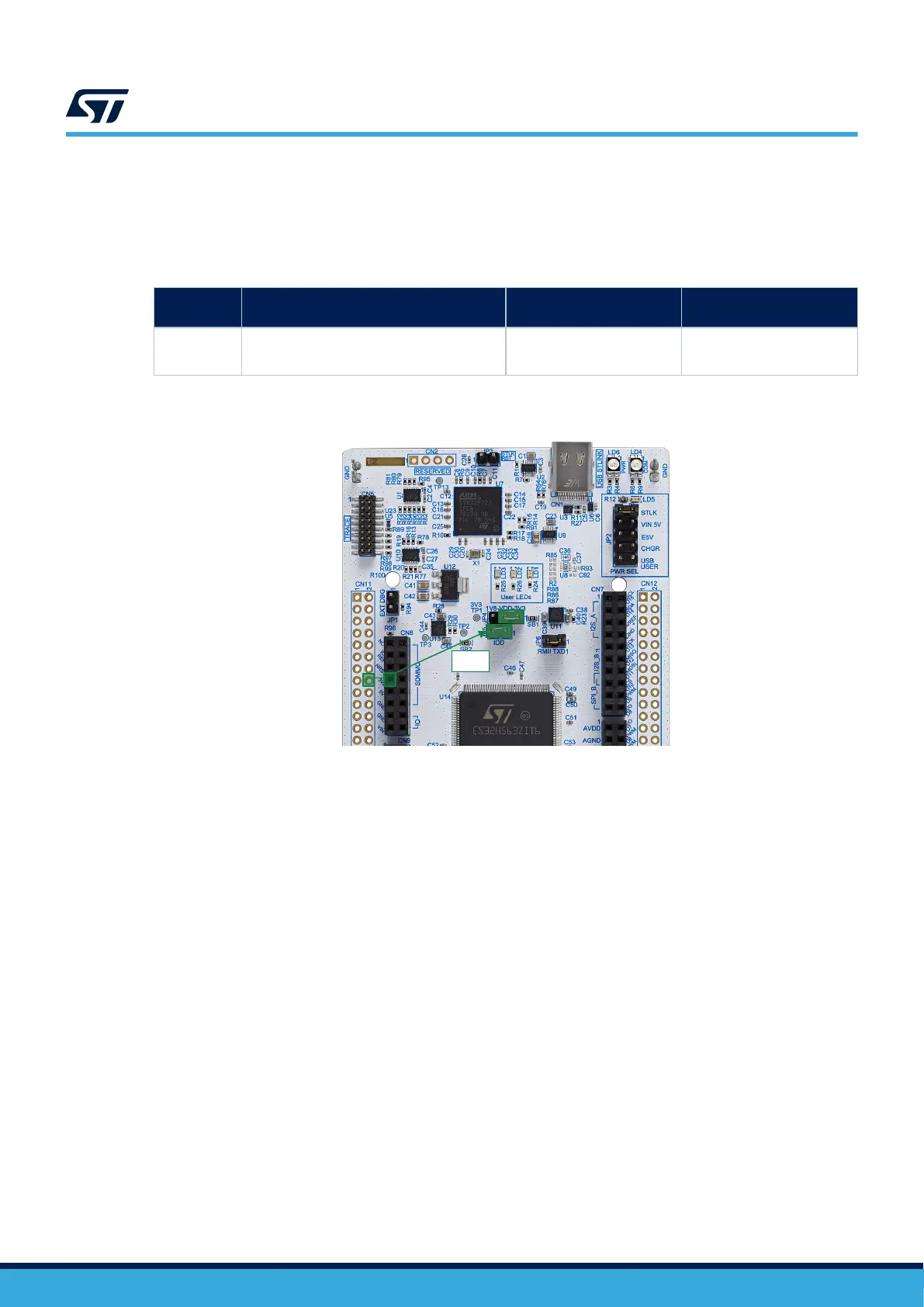
directly as the power input (refer to Figure 13 and Table 11). In this case, note that programming and debugging
features are unavailable as STLINK-V3EC is not powered.
Table 11. External power source 3V3_EXT (3.3 V, 1.3 A maximum)
Input power
name
Connector pins Voltage range Maximum current
3V3
CN8 pin 7
CN11 pin 16
3.0 to 3.6 V 1.3 A
Figure 13. Power supply input from 3V3_EXT (3.3 V)
DT59068V1
3V3_EXT
No
jumper
3V3
8.7 Debugging/programming when not using an external power supply
When powered by VIN (VIN 5 V) or 5V_EXT (E5V), it is still possible to use STLINK-V3EC for programming or
debugging only. In this case, it is mandatory to power the board first using VIN 5 V or E5V, then connect the USB
cable from CN1 to the PC. In this way, the enumeration succeeds, thanks to the external power source.
The following power-sequence procedure must be respected:
1. Configure the jumper JP2 [5-6] for E5V or [3-4] for VIN 5V.
2. Connect the external power source to VIN 5 V or E5V.
3. Power on the external power supply 7 V < VIN < 12 V to VIN 5 V, or 5 V for E5V.
4. Check that the green LED (LD5) is turned ON.
5. Connect the PC to the USB connector (CN1).
If this order is not respected, the following risks might be encountered:
1. If the board needs more than 300 mA current, the PC might be damaged, or the PC can limit the supplied
current. As a consequence, the board is not powered correctly.
2. If 300 mA is requested during enumeration, there is a risk that the request is rejected and the enumeration
does not succeed if the PC cannot provide such current. Consequently, the board is not power supplied. The
green LED (LD5) remains OFF.
UM3115
External power supply input 3V3_EXT (3.3 V, 1.3 A maximum)
UM3115 - Rev 2
page 18/44