6 Hardware layout and configuration
The STM32H5 Nucleo-144 board is designed around an STM32H5 series microcontroller in a 144-pin LQFP
package.
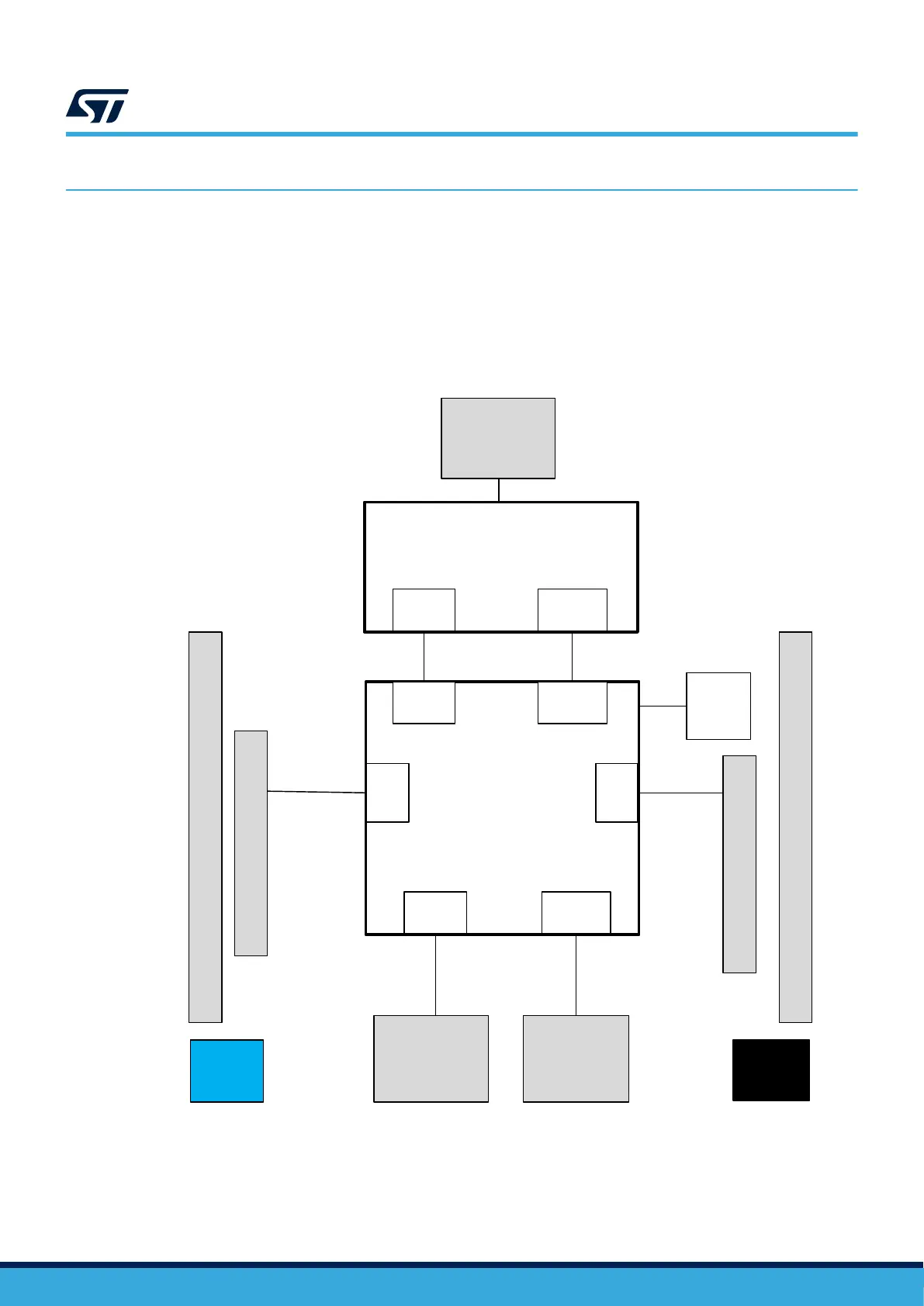
Figure 3 shows the connections between the STM32H5 and its peripherals (STLINK-V3EC, push-buttons, LEDs,
USB, Ethernet, ST Zio connectors, and ST morpho headers).
Figure 4 and Figure 5 show the location of these features on the STM32H5 Nucleo-144 board.
The mechanical dimensions of the board are shown in Figure 6.
Figure 3. Hardware block diagram
DT59060V1
Embedded
STLINK-V3EC
STM32
microcontroller
ST morpho extension header
ST morpho extension header
I/O
VCP
UART
Reset
button
(B2)
User
button
(B1)
I/O
Zio connector
LED1
LED2
LED3
USB Type-C
®
connector
Zio connector
RJ45
connector
USB Type-C
®
connector
SWD
SWD
VCP
UART
USB RMII
Note:
VCP: Virtual COM port
SWD: Serial Wire Debug
UM3115
Hardware layout and configuration
UM3115 - Rev 2
page 7/44

 Loading...


