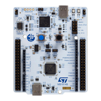
10 Board functions
10.1 LEDs
User green LED (LD1)
The user green LED (LD1) is connected to the PB0 STM32 I/O (SB43 ON and SB51 OFF) or PA5 (SB51 ON and
SB43 OFF) corresponding to the D13 ST Zio.
User yellow LED (LD2)
The user yellow LED (LD2) is connected to PF4.
User red LED (LD3)
The user red LED (LD3) is connected to PG4.
These user LEDs are ON when the I/O is in the HIGH state, and are OFF when the I/O is in the LOW state.
COM LED (LD4)
The tri-color (green, orange, and red) LED (LD4) provides information about the ST-LINK communication status.
LD4 default color is red. LD4 turns to green to indicate that communication is in progress between the PC and
STLINK-V3EC, with the following setup:
• Slow blinking red/OFF at power-on before USB initialization
• Fast blinking red/OFF after the first correct communication between PC and STLINK-V3EC (enumeration)
• Red LED ON when the initialization between the PC and STLINK-V3EC is complete
• Green LED ON after a successful target communication initialization
• Blinking red/green during communication with the target
• Green ON communication finished and successful
• Orange ON communication failure
Green PWR LED (LD5)
The green LED (LD5) indicates that the +5 V power supply is available on the STM32H5 Nucleo-144. This source
is available on CN8 pin 9 and CN11 pin 18.
STLINK POWER STATUS LD6
The tricolor LED (LD6) provides information about the STLINK-V3EC target power.
USB Type-C
®
green LED (LD7)
The green LED (LD7) indicates the V
BUS
presence on the user USB Type-C
®
connector (CN13).
10.2
Push-buttons
Blue user button (B1)
The user button is connected to the PC13 I/O by default (tamper support: SB54 ON and SB59 OFF) or PA0
(wake‑up support: SB59 ON and SB54 OFF) of the
STM32H5 series microcontroller
Black reset button (B2)
This push-button is connected to NRST and is used to reset the STM32H5 series microcontroller.
UM3115
Board functions
UM3115 - Rev 2
page 20/44

 Loading...


