UM2411 Rev 2 17/61
UM2411 Hardware layout and configuration
60
Table 3 details jumper and solder bridge settings used for the configuration of the power
supply of STM32H747I-DISCO.
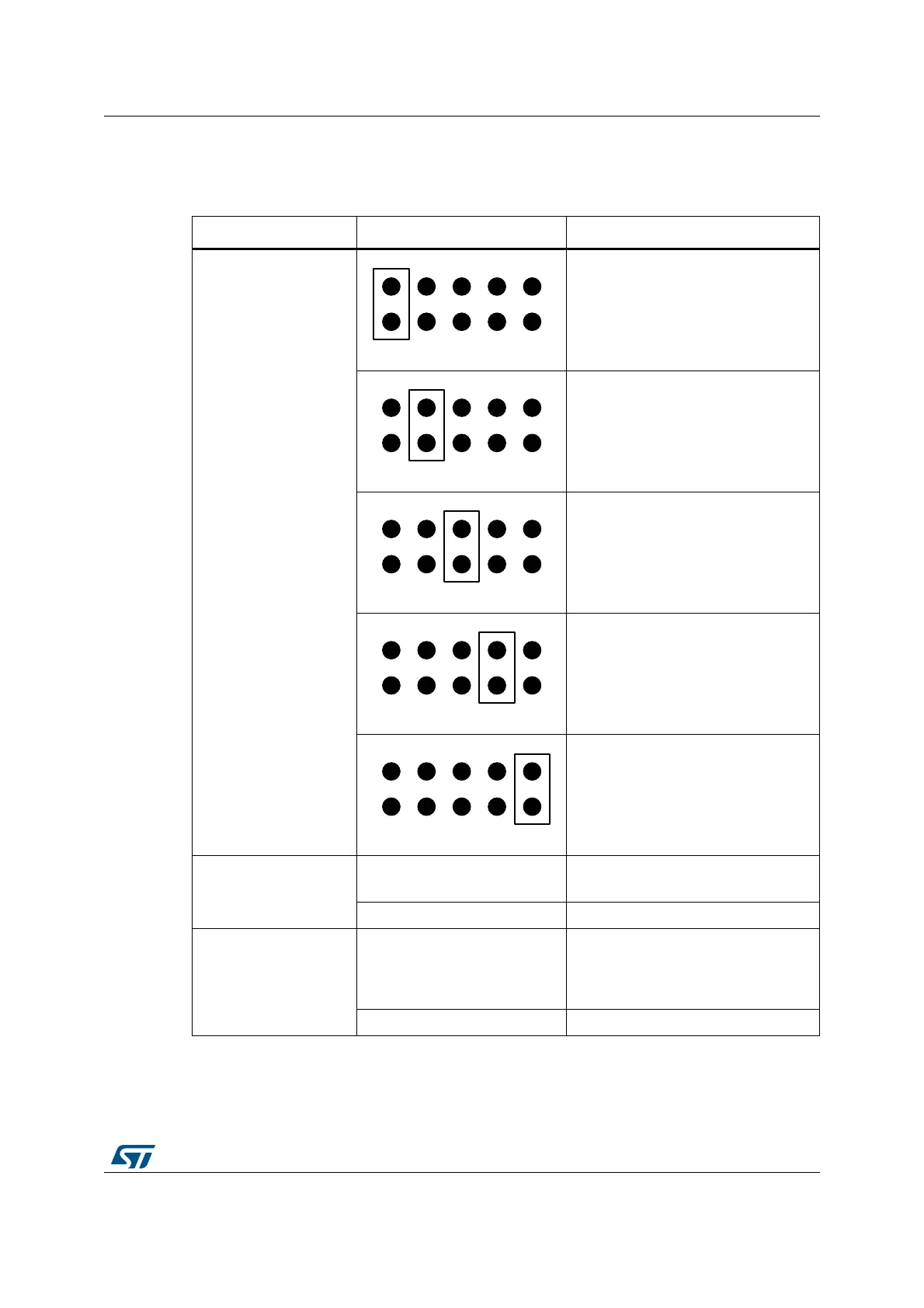
Table 3. Power-supply related jumper and solder bridge settings
Jumper / Solder bridge Setting Configuration
JP6
Power source selector
Default setting.
STM32H747I-DISCO is supplied
through the CN2 Micro-B USB
receptacle. Depend on host PC USB
port's powering capability declared in
the enumeration.
STM32H747I-DISCO is supplied
through the CN14 Micro-B USB
receptacle.
STM32H747I-DISCO is supplied
through the CN1 Micro-AB USB
receptacle.
STM32H747I-DISCO is supplied
through the pin 8 of CN8 (marked V
IN
).
STM32H747I-DISCO is supplied
through the CN2 Micro-B USB
receptacle.
Setting for powering the board through
CN2 using USB charger.
SB16
V
BAT
connection
SB16 ON
Default setting.
V
BAT
is connected to +3V3.
SB16 OFF V
BAT
is not connected to +3V3.
SB10
V
DD_USB
connection
SB10 ON
Default setting.
V
DD_USB
(VDDUSB terminal of
STM32H747XIH6) is connected to
V
DD_MCU
.
SB10 OFF V
DD_USB
is not connected to V
DD_MCU
.

 Loading...


