Connectors UM2411
32/61 UM2411 Rev 2
6.15 Camera module connector P1
An 8-bit camera module function is supported thanks to the 30-pin dedicated ZIF connector
P1. The reference of camera module to be used is STM32F4DIS-CAM. This module must
be connected with caution before powering the STM32H747I-DISCO Discovery board. The
camera module I²C addresses are 0x61 and 0x60. Camera is usable by default. Care must
be taken of GPIO sharing and multiplexing with other functions, in order to program the
good configuration. GPIO assignment and sharing:
• DCMI_SDA and DCMI_SCL I
2
C peripheral share with Pmod™/STMOD+ connector,
Arduino™ connector, and Audio DSI
SM
LCD
• Camera signals PA4, PC6, PC7, PB8, PB9, PD3 share with Pmod™
• Camera signals PC9 and PC11 share with SDIO
• Camera signal PA6 shared with Arduino™
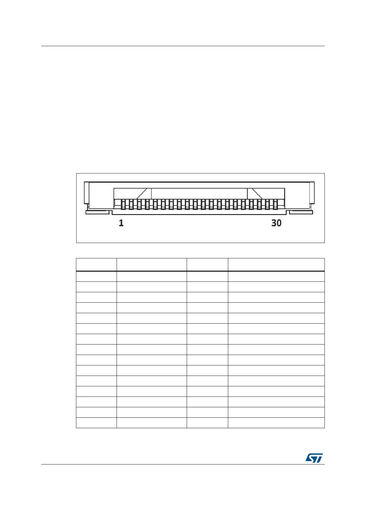
Figure 17. Camera module connector P1 (front view)
Table 18. Camera module connector P1
Pin number Description Pin number Description
1GND 16GND
2 NC 17 DCMI_HSYNC (PA4)
3NC 18NC
4 DCMI_D0 (PC6) 19 DCMI_VSYNC (PB7)
5 DCMI_D1 (PC7) 20 3V3
6 DCMI_D2 (PG10) 21 Camera_CLK (OSC_24M)
7 DCMI_D3 (PC9) 22 NC
8 DCMI_D4 (PC11) 23 GND
9 DCMI_D5 (PD3) 24 NC
10 DCMI_D6 (PB8) 25 DCMI_PWR_EN (PJ14)
11 DCMI_D7 (PB9) 26 RESET#
12 NC 27 DCMI_SDA (PD13)
13 NC 28 DCMI_SCL (PD12)
14 GND 29 GND
15 DCMI_PIXCK (PA6) 30 3V3

 Loading...


