UM2411 STMod+ GPIO sharing and multiplexing
UM2411 Rev 2 59/61
Appendix B STMod+ GPIO sharing and multiplexing
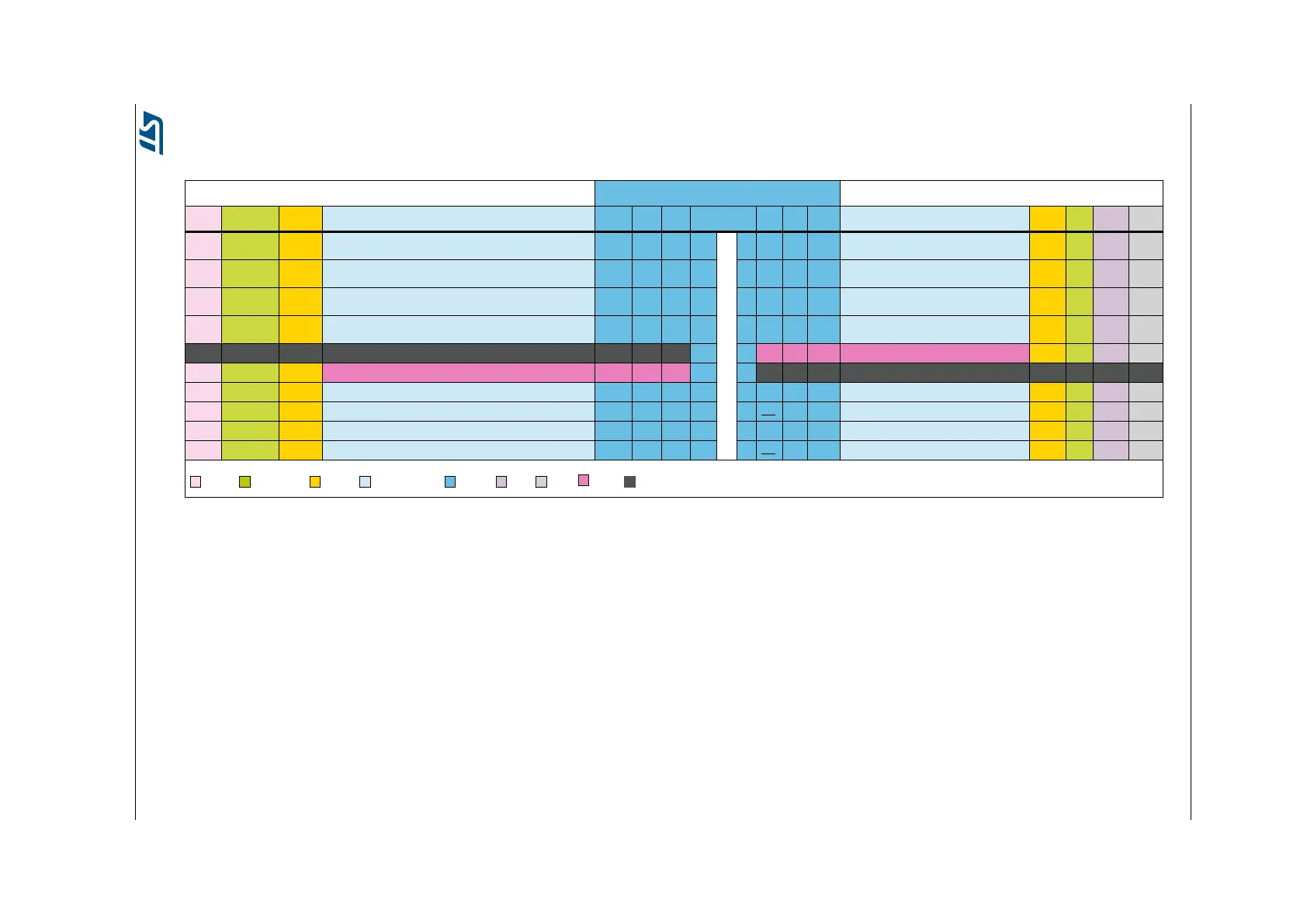
Table 22. STMod+ GPIO sharing and multiplexing
Shared or exclusive functions STMod+
(1)
Shared or exclusive functions
DFSDM ARD Pmod™ Some other Alternate Functions
(2)
Basic SB Port Pins Port SB Basic Some other Alternate Functions
(2)
Pmod™ ARD DFSDM DCMI
- -
CTSS2
CSN2
ADC123_INO, TIM5_CH1
CNA1_RX, USART1_CTS
CTSS2
NSS2
31
32
PA0
PA11
1
-
11 PC6 - INT TIM3_CH1, TIM8_CH1, USART6_TX INT - CK3 D0
DATA1
-
TXS3
MOSI2
CAN1_TXFD, USART2_RX
ADC123_IN13
TXS2
MOSI2
33
34
PD5
PC3
2 12 PJ13 - RST - RST - - -
DATA1
CKOUT
-
RXS3
MISO2
USART2_TX
ADC123_IN12
RXS2
MISO2
35
36
PD6
PC2
3 13 PA4 - ADC ADC12_IN4, TIM5_ETR, DAC1_OUT - A0 - HSYNC
- -
RTSS3
SCK2
CAN1_RXFD
TIM1_ETR, CAN1_TX, USART1_RTS
RTSS2
SCK2
37
38
PD4
PA12
4 14 PF8 - PWM ADC3_IN6, TIM13_CH1 - D3 - -
- - - - GND - GND 5 15 +5V - +5V - - - - -
- - - - +5V - +5V 6 16 GND - GND - - - - -
- SCL4 - TIM4_CH1 SCL4 - PD12 7 17 PC7 - GPIO TIM3_CH2, TIM8_CH2, USART6_RX - - - D1
CK2 - - TIM1_CH3N, TIM8_CH3N, TIM12_CH2, USART1_RX MOSI2 - PB15 8 18 PD3* - GPIO - - - CKOUT D5
DATA2 - - TIM1_CH2N, TIM8_CH2N, TIM12_CH1, USART1_TX MISO2 - PB14 9 19 PB9 - GPIO TIM4_CH4, TIM17_CH1, CAN1_TX, I2C1_SDA - - DATA7 D7
- SDA4 - TIM4_CH2 SDA4 - PD13 10 20 PB8* - GPIO TIM4_CH3, TIM16_CH1, CAN1_RX, I2C1_SCL - - CK7 D6
Legend:
= DFSDM = Arduino™ Uno = Pmod™ = Alternate Functions = STMod+ = CAM = DCMI = Supply = GND
1. Table 22 gives the description of the signals available on the STMod+ connector.
It also shows which signal is shared with other board connector or function.
The I
2
C bus on pins 19 / 20 might be shared with built-in discovery slave devices. Check the slave address of any new device when adding it to the bus.
2. RTSS2 stands for USART2_RTS,
CTSS2 stands for USART2_CTS,
RXS2 stands for USART2_RX,
TXS2 stands for USART2_TX,
MOSI2 stands for SPI2_MOSI,
MISO2 stands for SPI2_MISO,
NSS2 stands for SPI2_NSS,
SCK2 stands for SPI2_SCK,
SDA4 stands for I2C4_SDA,
SCL4 stands for I2C4_SCL,
RST stands for RESET,
INT stands for INTERRUPT.

 Loading...


