EN
ENGLISH
(Translation of the original instructions)
6. Fit the sleeve onto the steering column and
secure by fully inserting the pins. Lock the
steering column.
• Type “II” steering wheel
1. Slide the steering wheel sleeve (9:E) onto the
steering column (9:F) as far as it will go.
2. Align the holes in the sleeve with those in the
column.
3. Once the holes (9:G) have been aligned, in-
sert the two pins (9:H).
5.6 TOW BAR (10)
Fit the tow bar (10:B) to the rear of the machine.
Use the screws and nuts (10:A; 10:C).
Tightening torque 22 Nm.
5.7 QUICK RELEASE SUPPORTS (1:N)
The quick release supports and related instal-
lation instructions are supplied in a separate
package located in the machine's packaging.
Install the quick release supports on the front
machine semi-axles.
5.8 TYRE PRESSURE
For tyre pressure see chap. "00 TECHNICAL
SPECIFICATION TABLE"
5.9 ATTACHMENTS
To mount attachments, see the separate assem-
bly guide supplied with each attachment.
N.B. In this case the cutting device as-
sembly is considered an attachment.
6 CONTROLS
6.1 MECHANICAL ATTACHMENT LIFT PED-
AL (11:A)
It controls the lever (11: A1) used to bring the
attachments from the working position to the
transport position.
• Transport position: fully press the pedal down
and remove your foot, the pedal remains down.
• Working position: slowly press and release the
pedal.
Do not switch to the transport position
while the attachment is running. This
would destroy the drive belt.
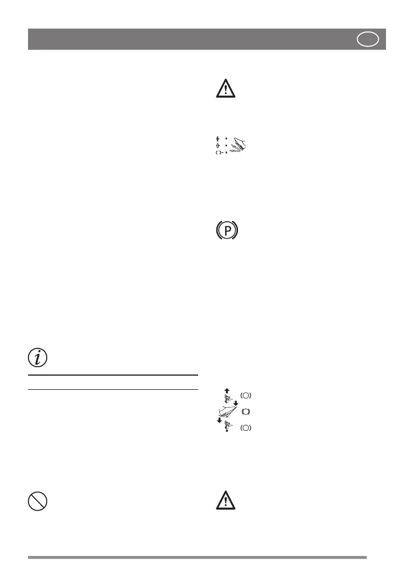
6.2 PARKING BRAKE PEDAL (11:B)
Never press the pedal while driving.
There is a risk of overheating the transmission.
The pedal (11: B) can assume the following
positions:
Released. Drive on. The parking brake
is not activated.
Half-pressed. Forward drive is disengaged. The
parking brake is not activated.
Fully pressed. Drive is disengaged. The parking
brake is fully activated but not locked. This posi-
tion is also used as an emergency brake.
6.3 PARKING BRAKE LOCK LEVER (11:C)
Locks the “brake” pedal in the fully pressed
position. This function is used to
lock the machine on slopes, dur-
ing transport, etc., when the engine is
stopped.
Lock:
1. Fully press the pedal down (11:B).
2. Move the latch (11:C) to the right.
3. Release the pedal (11:B);
4. Release the latch (11:C)
Unlock:
1. Press and release the pedal (11:B).
6.4 DRIVE PEDAL (11:D)
The pedal determines the gear ratio between the
engine and the drive wheels (= speed).
When the pedal is released, the service brake is
activated.
- Pushing the pedal forward, - the ma-
chine moves forward.
- When there is no load on the pedal -
the machine is stationary.
- Pushing the pedal back - the ma-
chine moves in reverse.
- By reducing the pressure on the ped-
al - the machine brakes.
There is a plate on the top section of the pedal
which can be adjusted to suit the driver's foot.
If the machine does not brake as ex-
pected when the pedal is released, use
the left pedal (11: B) as an emergency
brake.
13
 Loading...