Edition
2016
Workshop Manual
PARK 120 - PARK 220
Chapter
7 Electrical system
Page
52
7.1 Description
The cables are connected to the actual components with tab or screw connectors and in
some cases with multi-contact connectors.
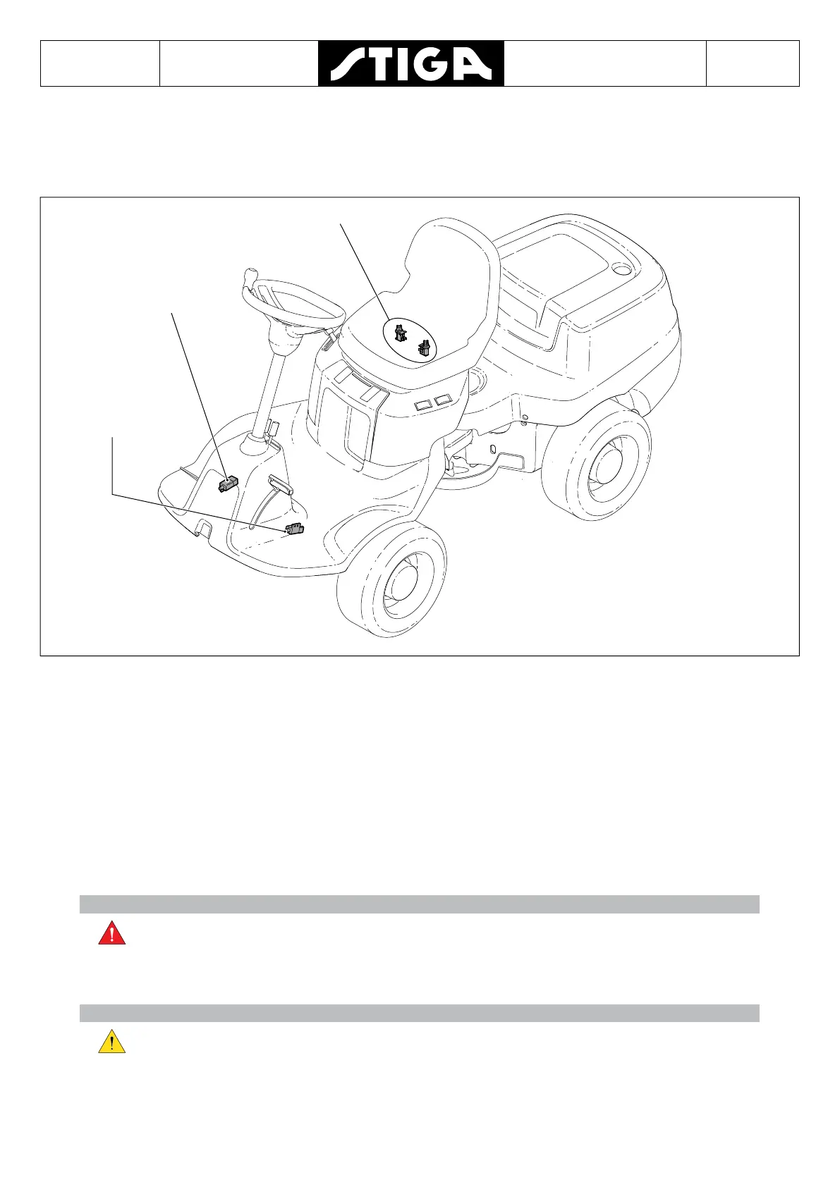
Seat switch
Safety switch
parking brake
Safety switch
lift pedal
The electrical system consists of several safety circuits.
Therefore certain controls and pedals are tted with switches. The switches are shown in
the gure below.
The signal from the switches is used to open/close the circuit when a prohibited action is to
be carried out.
The wiring diagram must be read for full understanding of the electrical system of a special
machine model.
All power apart from the starting circuit is protected by the fuse.
7.1.1 Cable holders
Warning!
It is important that all cable holders are securely fastened. If they are not there is
a risk of short circuits and re.
All electrical cables are mounted on the chassis with cable holders. When removing or
replacing the electrical cables new cable holders must be installed in the original positions.
Attention!
Loose electrical cables can cause unnecessary wear to the components This
can lead to short circuits, damage to plastic protection, paintwork etc.

 Loading...