59FS 240 C, FS 260 C, FS 360 C, FS 410 C, FS 460 C-M
After ending the test procedure,
disconnect the test lead and reseal
the diagnostic jack with the plug.
7.3.3 Check screwed and plug
connections as well as
switch
– Carry out test preparations,
b 7.3.1
There must be a reliable connection
for communication between control
unit, switching device and solenoid
valve. If communication between
control unit and solenoid valve is
interrupted or faulty, the control unit
does not initiate an ignition spark.
– In the event of a malfunction or if
there is no ignition spark, first
check the plug connections and
wiring harness between control
device and solenoid valve
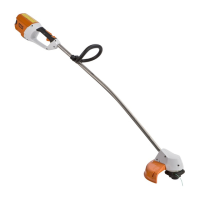
Screws (1) must be tight.
Leads (arrows) must be seated
completely and firmly in the cable
lugs.
1
5904RA277 TG
1
Plug (1) must be seated completely
and firmly in the recess of the
solenoid.
: If necessary, remove plug (1) and
check contacts
: Set choke lever (1) to
position }; the cam on the
lever (2) must actuate the
microswitch (arrow)
– Clicking noise
1
5904RA278 TG
2
5904RA279 TG
1
7.3.4 Checking the solenoid
valve
– Carry out test preparations,
b 7.3.1
– Check contacts and operation,
b 7.3.3
– Move choke lever to position "F"
– Connect the test lead, b 7.3.2
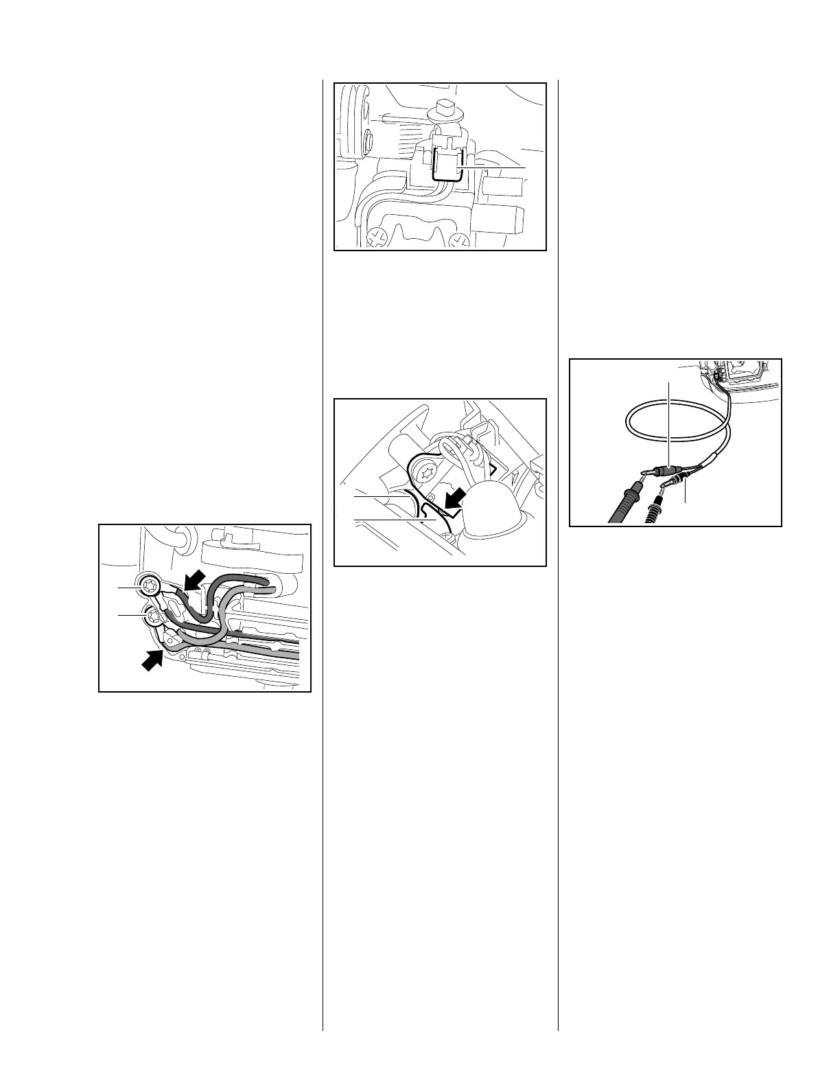
Measuring resistance
: Measure resistance between
plugs (1) and (2) of the M-Tronic
test lead
Target value: between 28 and
42 ohms
– If the target value is not attained,
check electrical leads for
interruption, e. g., due to cable
breakage between solenoid
valve and diagnostic jack
5904RA280 TG
2
1

 Loading...