0703-001-700 Rev-C EN
www.stryker.com 15
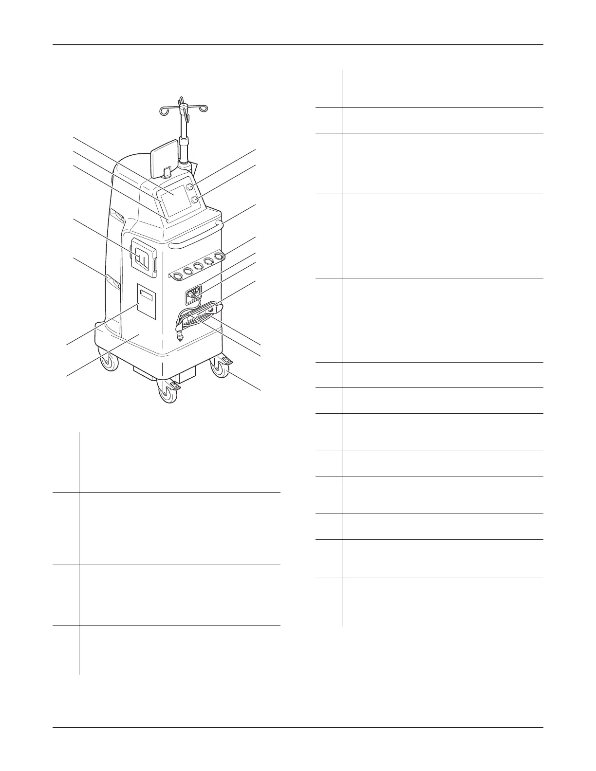
6.1.2 Rover Back View
L
Q
M
N
V
W
U
T
S
O
Z
AA
AB
Y
X
R
P
Figure 9 – Rover Back View
L Vacuum Pump (not shown) – Creates suction
for both canisters. If the suction level decreases
in either canister due to an open manifold port,
the suction level in the other canister may
decrease.
M Fluid Suction Filter Compartment – Allows
for the installation and removal of a disposable
fluid suction filter. This filter (included) provides
HEPA filtration of the air from the 20-liter and
4-liter canisters. See Section 9 Inspection and
Maintenance.
N Canister Viewing Door/Handle (four) – Each
canister has two viewing doors with a handle.
These doors may be opened during operation to
reveal the contents or closed during relocation to
conceal the contents.
O Smoke Evacuator Filter Compartment – Allows
for the installation and removal of a disposable
smoke evacuator filter (not included) with an
ULPA efficiency rating.
P HIGH VACUUM/HIGH FLOW Continuous
Surgical Suction Range: 50 to 520 mm-Hg, –
See Section 14 Specifications.
Q Control Panel – Consists of a touch-sensitive
main display and two suction control dials.
R Main Display – Provides the primary operating
interface via a touch-sensitive control screen.
The display also provides important status
information and alarm status (Figure 11 and
Figure 13).
S 4-Liter Suction Control Dial – Allows for the
rotary adjustment of the suction LIMIT value of
the 4-liter canister; clockwise increases the value
and counterclockwise decreases the value. The
suction value will appear on the main display as
a LIMIT value. See Table 5 Suction Limit Ranges
and Colors.
T 20-Liter Suction Control Dial – Allows for the
rotary adjustment of the suction LIMIT value of
the 20-liter canister; clockwise increases the
value and counterclockwise decreases the value.
The suction value will appear on the main display
as a LIMIT value. See Table 5 Suction Limit
Ranges and Colors.
U Handle – Allows for relocation and positioning of
the rover.
V Manifold Holder – Allows for the storage of new,
unused manifolds.
W Power Cord Receptacle/Switch – Allows for the
connection and application of facility power to
the rover.
X Serial Number Label – Identifies the serial
number information of the rover.
Y Specification Label – Identifies the part
number information of the rover. See Section 14
Specifications.
Z Power Cord Bracket – Allows for the wrapping
and storage of the supplied power cord.
AA Power Cord with Retainer – The supplied power
cord is used to connect the rover to facility
power. The retainer keeps the cord in place.
AB Casters (four) – Four swivel casters provide
mobility for the rover to roll across a floor.
The two rear casters have locks to prevent
unintended movement during operation.
0000160552, Rev. C Effective Date: Nov 25, 2015 1:43:15 PM
Print Date: Nov 25, 2015 02:19:13 PM
 Loading...