18 www.stryker.com
EN 0703-001-700 Rev-C
6.2.3 Screens, Dialogs, and Drop-downs
6.2.3.1 Main Display Control Screen Areas
Suction ON
Evacuate Smoke
Reset Volumes
Settings
4L Light
Empty 4L
Canister
4 L
Suction Limit
50
mm-Hg
44
Actual:
mm-Hg
used
used
Stop Suction
OFF
MAX
HIGH
MED
LOW
200 mL
since last reset
0 mL
since last reset
120
mm-Hg
115
Actual:
mm-Hg
OFF
MAX
MED
LOW
HIGH
20 L HIGH suction
C D FE HG
I
J
K
B
A
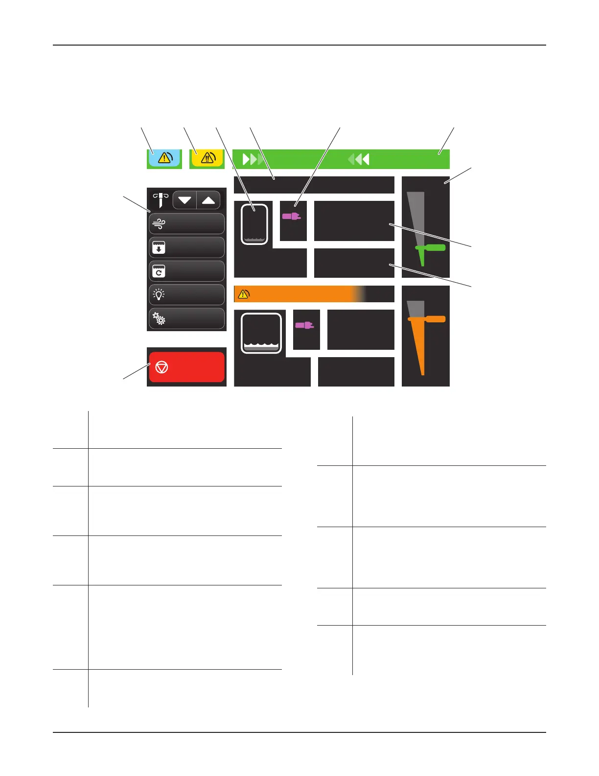
Figure 13 – Roving Mode (Control) Screen
A Suction Control Area – Provides a toggle
button to control the presence or absence of
fluid suction.
B Control Menu Area – Provides buttons to
control the primary functions of the rover
(Figure 12).
C Notification Message Area – Indicates when
a low priority alarm condition has occurred
(Figure 16); touch to access the drop-down list
and/or message. See Section 17 Glossary.
D Error Message Area – Indicates when a
medium priority alarm condition has occurred;
touch to access the drop-down list and/or
message. See Section 17 Glossary.
E Canister Information Area (two) – Identifies
the specific canister; also provides fluid volume
information via a 4L or 20L canister symbol
and a fluid volume reading. If the canisters’
volumes are reset, the words ‘since last reset’
will appear. See Table 9 Canister Symbol
Colors.
F Suction Status Area (two) – Indicates
the suction status of a canister, including
STOPPED, PAUSED, or HIGH.
G Manifold Indicator Area (two) – Indicates
the status of the manifold installed in the
receptacle. Status conditions include new or
used. See Table 8 Manifold Symbol Colors.
H Title Area – Indicates status, including system
setup, suction ON, suction OFF, EMPTYING
4-liter canister, and PREFILLING 4-liter
canister. See Section 17 Glossary for the
definition of prefilling.
I Suction Gauge Area (two) – Indicates the
suction selected with the rotary suction control
dial, including OFF, LOW, MEDium, HIGH, or
MAXimum. See Table 5 Suction Limit Ranges
and Colors.
J Suction LIMIT Value Area (two) – Indicates
the selected suction limit value obtained by
using the rotary suction control dial.
K ACTUAL Suction Value Area (two) – Indicates
the actual suction value present in the canister.
The ACTUAL value may fluctuate and could be
significantly lower than the suction LIMIT value.
0000160552, Rev. C Effective Date: Nov 25, 2015 1:43:15 PM
Print Date: Nov 25, 2015 02:19:13 PM
 Loading...